
Installation Manual Instruction Manual
Assembly
900-0123-01-00 Rev B 13
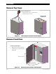
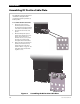
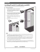
Remove Interior Cover
In order to make any wiring connections or install components, the interior cover must be removed to
expose the interior of the enclosure.
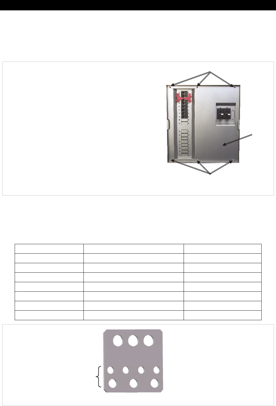
Figure 13 Removing the Interior Cover from the GSLC
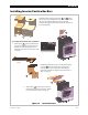
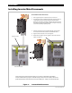
Installing the Internal Hardware
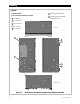
Table 1 Bus Bar and Circuit Breaker Size and Torque Requirements
Item Terminal/Bolt Size Torque Requirements
Inverter Positive Bus Bars M8 60 in-lb (6.8 Nm)
Shunt Bolts 3/8" 60 in-lb (6.8 Nm)
DC Positive Cable Plate Top Holes (x3) 60 in-lb (6.8 Nm)
Bottom Holes (x7) 50 in-lb (5.7 Nm)
Circuit Breaker Studs M8 20 in-lb (2.3 Nm)
1/4" 35 in-lb (4.0 Nm)
5/16" 50 in-lb (5.7 Nm)
3/8" 225 in-lb (25.5 Nm)
Figure 14 DC Positive Cable Plate
Top Holes
Bottom Holes
0.5" (12.7 mm)
0.31" (8 mm)
0.4" (10 mm)
Remove (x3)
Remove
(
x3
)
Interior
Cover
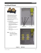
To Remove the Interior Cover:
1. Remove the three screws along the top of the
enclosure (with one star washer).
2. Remove the three screws along the bottom of
the enclosure (with one star washer).
3. Lift the front cover off the enclosure.