
User Guide


Specifications
900-0112-01-00 Rev B 51
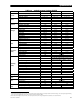
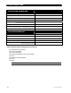
Table 21 24-Volt Inverter Settings (MATE3)
Field Item Default Minimum Maximum
Sensitivity (see page 14 for increments)
6 0 50
Pulse Length
8 4 20
Search
Pulse Spacing
60 AC cycles 4 AC cycles 120 AC cycles
Input Type Grid Grid or Gen
Input Support Y Y or N
Grid Input AC Limit
25 Aac 2.5 Aac 30 Aac
Gen Input AC Limit
25 Aac 2.5 Aac 30 Aac
AC Input and
Current Limit
Charger AC Limit
5.5 Aac 0 Aac 6 Aac
LowerVoltage Limit
208 Vac 140 Vac 220 Vac
Upper Voltage Limit
252 Vac 250 Vac 280 Vac
Grid AC Input
Voltage Limits
Transfer Delay
6 AC cycles 0 AC cycles 240 AC cycles
LowerVoltage Limit
208 Vac 140 Vac 220 Vac
Upper Voltage Limit
252 Vac 250 Vac 280 Vac
Transfer Delay
6 AC cycles 0 AC cycles 240 AC cycles
Gen AC Input
Voltage Limits
Connect Delay
0.5 minutes 0.2 minutes 15 minutes
AC Output
AC Output
230 Vac 210 Vac 250 Vac
Cut-Out Voltage
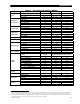
21 Vdc 18 Vdc 24 Vdc
Low Battery
Cut-In Voltage
25 Vdc 20 Vdc 28 Vdc
Absorb Voltage
28.8 Vdc 26 Vdc 32 Vdc
(Absorb) Time
1.0 hours 0.0 hours 24.0 hours
Float Voltage
27.2 Vdc 24 Vdc 30 Vdc
(Float) Time
1.0 hours 0.0 hours 24.0 hours
Battery Charger
Re-Float Voltage
25 Vdc 24 Vdc 26 Vdc
Equalize Voltage
29.2 Vdc 28 Vdc 34 Vdc
Battery Equalize
(Equalize) Time
1.0 hours 0.0 hours 24.0 hours
Aux Mode Cool Fan
Remote, Load Shed, Gen Alert, Fault, Vent Fan,
Cool Fan, Divert DC, Divert AC, or AC Drop
(Load Shed) Enable Voltage
22 Vdc 20 Vdc 28 Vdc
(Gen Alert) ON Voltage
22 Vdc 20 Vdc 28 Vdc
(Gen Alert ON) Delay
4 minutes 0 minutes 240 minutes
(Gen Alert) OFF Voltage
28 Vdc 24 Vdc 36 Vdc
(Gen Alert OFF) Delay
9 minutes 0 minutes 240 minutes
(Vent Fan) Enable Voltage
26 Vdc 20 Vdc 32 Vdc
(Vent Fan) Off Period
5 minutes 0 minutes 30 minutes
(Divert DC or AC) Enable Voltage
29.2 Vdc 24 Vdc 32 Vdc
Auxiliary
Output
(Divert DC or AC) Off Delay
30 seconds 0 seconds 240 seconds
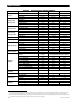
Inverter
Stacking
Stack Mode Master Master, OB Slave L1, 3p Classic B , 3p Classic C
Master Adjust Only
0 0 7
Power Save
Slave Adjust Only
1 1 15
Grid Tie Enable Y Y or N
Sell Voltage
23.6 Vdc 20 Vdc 30 Vdc
Grid-Tie Sell
Grid Tie Window IEEE IEEE or user
Input Voltage
9
-1 -3 1
Output Voltage
9
-1 -3 1
Calibrate
Battery Voltage
10
0.0 -0.4 0.4
9
These values represent an adjustable setting with a total range of 4 Vac. The default value of -1 means the calibration will subtract 1 volt from the measured
value. The range of settings allow up to 1 volt to be added to the measured value, or up to 3 volts to be subtracted from it. The result is also displayed.
10
These values represent an adjustable setting with a range of ± 0.4 Vdc from the measured value. The range of settings allow up to 0.4 volts to be either added
or subtracted from the measured value (in increments of 0.2 Vdc). The result is also displayed.