
- Outback Power Systems, Inc. Battery Charger User Manual
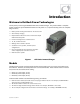

Introduction
10 900-0113-01-00 Rev A
Each model inverter has a single phase output marked with this symbol:
Each inverter puts out a sine wave waveform marked with this symbol:
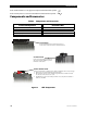
Components and Accessories
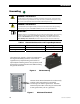
Table 2 Components and Accessories
Installed Components Included in Box
Battery Terminal Cover, red GFX Series Installation Manual
(this book)
Battery Terminal Cover, black GFX Series Operator’s Manual
AC Conduit Plate “WARNING ELECTRICAL SHOCK” sticker
DC Cover (DCC) Remote Temperature Sensor (RTS)
Silicone Grease Packet
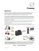
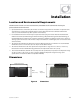
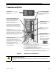
Figure 2 GFX Components
DCC (DC COVER)
Covers the DC terminal area and provides space to
mount other com
p
onents such as a DC current shunt.
AC CONDUIT PLATE
Connects to AC conduit fo
r installations
which do not utilize OutBack’s optional
FLEXware conduit boxes.
BATTERY TERMINAL COVER
Protects terminals from accidental contact. Made of stiff plastic with a snap-on design.
Always keep covers installed during normal operation.
When required, remove covers carefully using a flat-blade screwdriver inserted
into the slots on the sides of each cover.
The DCC does not replace the battery terminal covers; they must be installed in
addition to the DCC.