
- Outback Power Systems, Inc. Battery Charger User Manual


Installation
30 900-0113-01-00 Rev A
Parallel Stac u
erters)
When installing a paral
Parallel stacking requires a system display and a HUB.
ogrammed as
Master
. (See the
elow the other inverters allows the master to avoid
1
during programming.
-phase).
s, local codes may require the inverter breakers to be located at
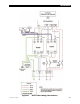
king (D al-Stack and Larger)
In parallel stacking, two or more inverters are stacked to create a single, common 120 Vac bus.
All inverters share a common input (AC source) and run loads on a common output.
Up to ten inverters may be installed in a parallel arrangement. The example on this page shows three
inverters. The wiring diagram on the next page shows four.
3.9 kVA
120 Vac
1.3 kVA 120 Vac
1.3 kVA 120 Vac
1.3 kVA 120 Vac
Figure 22 Example of Parallel Stacking Arrangement (Three Inv
lel system, the following rules must be observed.
The inve
rter that is mounted physically lowest is always the master and is pr
system display manual for programming.) Mounting b
heat buildup and remain relatively cool, as it sees the greatest duty cycle.
The master must be connected to port 1 of the HUB. Other inverters must not be selected as master.
All slave inverters, regardless of quantity, should be selected as
OB Slave L
All inverter wiring and input breakers must be sized for 60 Aac or less.
All inverters must be of the same model.
The AC input (generator or utility grid) must be 120 Vac at 60 Hz (single
When wiring the AC source to the inverter
the bottom of the main panel. This prevents overloading of the AC bus.