
- Outback Power Systems, Inc. Battery Charger User Manual

Installation
22 900-0113-01-00 Rev A
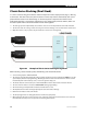
Accessory Wiring
RTS port
T
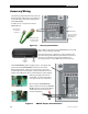
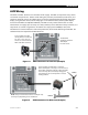
he AC Wiring Compartment Board has ports for
both the Remote Temperature Sensor (RTS) and
the system display. (The system display port is
labeled MATE/HUB.)
If a HUB is in use, it occupies the inverter’s
MATE/HUB port.
RTS cable (RJ11,
4-conductor,
telephone)
MATE cable (RJ45,
8-conductor, CAT5
non-crossover)
MATE/HUB port
Figure 12 Accessory Connections
See the Operator’s
Manual for more
information on
the RTS.
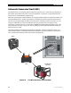
Figure 13 ON/OFF Jumper and Connections
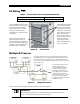
MATE
port
Additional
Ports
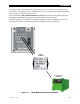
When a HUB occupies the inverter’s MATE/HUB port, the system
display connects directly to the HUB.
Inverters plug into ports 1 and above. Charge controllers and
other devices plug into additional ports after the last inverter is
connected. See Stacking on page 27 for information on
connecting inverters. See the HUB manual for other devices.
T
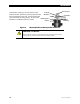
he INVERTER ON/OFF jumper bridges two pins. This jumper (JP1)
parallels the two INVERTER ON/OFF terminals on the Control
Wiring Terminal Block. If either set of connections is closed, the
inverter is ON. (Because the jumper is factory-installed, the inverter
usually remains ON unless given a command by the system display.)
Removing the jumper will turn the
inverter OFF. To remove the jumper,
use long-nose pliers or a similar tool.
Once the plastic INVERTER ON/OFF
jumper has been removed, the INVERTER
ON/OFF terminals on the Control Wiring
Terminal Block can be used to wire a
manual on/off switch.
Jumper On
Jumper Off