
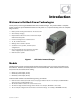
- Outback Power Systems, Inc. Battery Charger User Manual

Installation
16 900-0113-01-00 Rev A
Tools Required
Wire cutters/strippers
Torque wrenches
Assorted insulated screwdrivers
DVM or Voltmeter
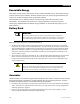
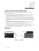
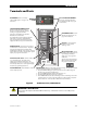
Mounting
It is easier for two people to install the GFX inverter due to its weight.
The unit must be secured with appropriate fasteners to a sturdy mounting surface capable of supporting its
weight. OutBack cannot be responsible for damage if inadequate fasteners are used.
The unit has four mounting holes, one in each corner. Use fasteners in all four corners for a secure
installation.
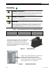
Due to the variance in other mounting methods, OutBack only endorses the use of FLEXware or previous
versions of its mounting plate. Use M6 x 20 mm machine screws, one per corner, to attach the inverter to
the mounting plate. Follow the instructions with each mounting system.
If mounting the inverter on other surfaces such as plywood, wall studs, or masonry, use appropriate
fasteners to support its weight. OutBack cannot be responsible for damage to the product if it is attached
with inadequate fasteners.
Mount and secure each component before attaching any wiring.
When the inverter is used with other metal chassis, make sure that all chassis are grounded appropriately.
(See the grounding instructions on page 18.) Grounding other chassis may involve metal-to-metal contact,
or sepa
rate gr
ound wires.
IMPORTANT:
If using an OutBack FLEXware Mounting Plate, avoid large air gaps behind the plate.
These can result in louder mechanical noise during heavy inverting or charging.