GFX Series Inverter/Charger GFX1312 GFX1424 GFX1548 Operator’s Manual
About OutBack Power Technologies OutBack Power Technologies is a leader in advanced energy conversion technology. Our products include true sine wave inverter/chargers, maximum power point tracking charge controllers, system communication components, as well as breaker panels, breakers, accessories, and assembled systems. Contact Information Telephone: Address: E-mail: Web Site: +1.360.435.6030 (North America) +1.360.618.4363 (Technical Support) +1.360.435.6019 (Fax) +34.93.654.
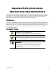
Important Safety Instructions READ AND SAVE THESE INSTRUCTIONS! This manual contains important safety instructions for the GFX Series inverters. Read all instructions and cautionary markings on the inverter and on any accessories or additional equipment included in the installation. Failure to adhere to these instructions could result in severe shock or possible electrocution. Exercise extreme caution at all times to prevent accidents.
Important Safety Instructions Definitions The following is a list of initials, terms, and definitions used in conjunction with this product. Table 1 Terms and Definitions Term Definition AC Alternating Current; refers to voltage produced by the inverter, utility grid, or generator.
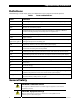
Table of Contents Important Safety Instructions ........................................................................1 Audience .................................................................................................................................................................................1 Symbols Used ........................................................................................................................................................................1 Definitions........
Table of Contents Specifications .............................................................................................43 Specifications for Model GFX1312 .............................................................................................................................. 43 Specifications for Model GFX1424 .............................................................................................................................. 44 Specifications for Model GFX1548 ........................
Table of Contents List of Tables Table 1 Table 2 Table 3 Table 4 Table 5 Table 6 Table 7 Table 8 Table 9 Table 10 Table 11 Table 12 Table 13 Table 14 Table 15 Table 16 Table 17 Table 18 Table 19 Terms and Definitions..................................................................................................................... 2 Battery LED Values..........................................................................................................................11 Status LED Quick Reference ....
Table of Contents List of Figures Figure 1 Figure 2 Figure 3 Figure 4 Figure 5 Figure 6 Figure 7 Figure 8 Figure 9 6 GFX Series Inverter/Charger.......................................................................................................... 7 AC Wiring Compartment................................................................................................................ 9 LED Indicators..........................................................................................................
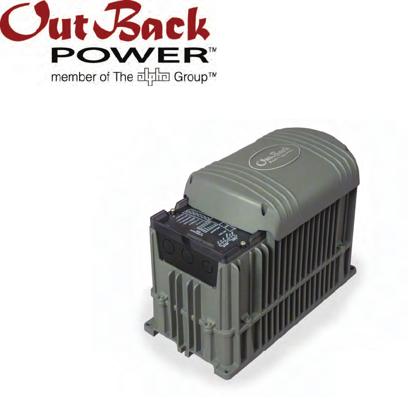
Introduction Welcome to OutBack Power Technologies Thank you for purchasing the OutBack GFX Series Inverter/Charger. This product offers a complete power conversion system between batteries and AC power. It can provide backup power or complete off-grid service.
Introduction System Display and Controller The GFX inverters have no external controls. They can operate normally without an external control or interface. Basic modes and settings are pre-programmed at the factory. However, if the pre-programmed settings need adjustment, a remote system display must be used for changing those settings and for more detailed monitoring activities. Modes and settings cannot be changed without the system display.
Operation Functional Test Pre-startup Procedures 1. 2. 3. 4. Ensure all DC and AC breakers or fuses are disconnected. Double-check all wiring connections. Inspect the work area to ensure tools or debris have not been left inside. Verify battery voltage using a digital voltmeter (DVM). Confirm the voltage is correct for the inverter model. Confirm the polarity. 5. Connect the system display (if present). CAUTION: Equipment Damage Incorrect battery polarity will damage the inverter.
Operation 5. If the INVERTER LED (green) is not illuminated, turn on the inverter using the system display or external switch. 6. Check the STATUS LEDs. Confirm that the INVERTER LED (green) is illuminated. 7. Using a DVM, verify 120 Vac between the AC HOT OUT and AC NEUTRAL OUT terminals. Do not turn on any AC breakers or disconnects at this time. 8. Perform all programming for stacking, battery charging, AC current, generator starting, and any other functions.
Operation LED Indicators AUX LED (see page 27) BATTERY LEDs STATUS LEDs Figure 3 LED Indicators BATTERY LEDS The battery LEDs show the approximate battery state. (See IMPORTANT note below.) The BATTERY LEDs are independent of STATUS LEDs. Any STATUS LED could accompany any BATTERY LED based on certain conditions. Common combinations are noted. A GREEN LED means the batteries have an adequate charge at that time. It does not always mean they are full.
Operation STATUS LEDS GREEN Solid: The inverter is ON and providing power. If accompanied by solid yellow LED, unit is selling power to the utility grid. (See page 23 for a description of the Sell function.) Flashing: The inverter has been turned ON but is idle. May be accompanied by the yellow LED. If not accompanied by the yellow LED, the unit in inverting mode and is idle due to lack of demand. This can be because the unit is in Search mode. (See page 14 for a description of Search.
Operation Description of Functions All items identified as settable or adjustable have set points which can be accessed using the remote system display. (See the system display manual for instructions on locating these set points.) The default settings and ranges of adjustment are listed near the end of this book, beginning on page 47. Inverting A GFX inverter uses a transformer and a high-frequency H-Bridge FET design to convert DC voltage from batteries into AC voltage that is usable by AC appliances.
Operation Search An automated search circuit is available to minimize the power draw when no loads are present. When enabled, the inverter does not always deliver full output. The output is reduced to brief pulses with a delay between them. These pulses are sent down the output lines to see if a resistance is present. In effect, the pulses “search” for a load. If one is detected, the inverter’s output increases to full voltage so that it can power the load.
Operation AC Current Settings The AC current settings control the amount of current that the inverter draws from the source(s). The amount of current is controlled by the grid or generator limit settings. These settings should be adjusted to match the size of the input breaker or circuit which is to be protected. In the MATE system display, if the ac transfer control menu is set to grid, the inverter uses the grid settings. If the menu is set to gen, the inverter uses the generator settings.
Operation Generators A generator should be sized to provide enough power for both loads and battery charging. The generator needs a single circuit which is sized to provide current to all inverters on a given phase or leg. It is usually recommended that the generator be sized at twice the wattage of the inverter system. Many portable generators may not be able to maintain AC voltage or frequency for long periods of time if they are loaded more than 80% of rated capacity.
Operation Grid/Generator Support A system display is required to control this feature. When this feature is enabled, the inverter limits the current draw from an AC source, augmenting it with additional current from the batteries when necessary. This helps prevent overloading a small AC breaker or generator during short-term use. Initially, the AC source current is used for both loads and battery charging.
Operation Battery Charging IMPORTANT: Battery charger settings need to be correct for a given battery type. Always follow battery manufacturer recommendations. Making incorrect settings, or leaving them at factory default settings, may cause the batteries to be undercharged or overcharged.
Operation The initial DC current is the maximum current the charger can deliver. It will begin at the charger’s specified maximum, but will gradually decrease as the voltage increases. This is a tradeoff in wattage and is normal for the charger. Absorption Stage This is the second stage of charging. It is a constant-voltage stage. Current varies as needed to maintain the voltage, but will typically decrease to a very low number over time.
Operation Note: If the MATE’s ac transfer control menu is set to gen, the charger skips both Sell and Silent, and proceeds directly to Float stage. (It will remain in Float until a new charge cycle is required, possibly through loss of AC power.) If ac transfer control is set to grid, the charger goes through Silent as noted and proceeds to Float only when the batteries drop to the Refloat voltage level. (See pages 14 and 15, and the MATE manual, for more information on ac transfer control.
Operation New Charging Cycle If the AC source is lost or disconnected, the unit will return to inverting mode if enabled. The battery voltage will begin to decrease due to loads or natural loss. When the AC source is restored, the inverter will return to the charging cycle. If the batteries drop below the Rebulk voltage, the inverter will restart the cycle, beginning at Bulk stage. If the batteries do not drop below Rebulk, the charger will not enter the Bulk stage and will return to its previous stage.
Operation Equalization follows the same pattern as standard three-stage charging, as shown in Figure 4. However, instead of the Absorption voltage and time set points, it is controlled by the equalize set point and equalize time period settings in the system display. Equalization is normally performed only on flooded lead-acid batteries. The schedule for equalization varies with battery use and type, but it is usually performed every few months.
Operation Selling IMPORTANT: Selling power to the utility company requires the authorization of the local electric jurisdiction. How the local utility company handles this will depend on their policies on this issue. Some may pay for power sold; others may issue credit. Some policies may prohibit the use of this mode. Please check with the utility company and obtain their permission before using this mode. The GFX inverters are grid-interactive.
Operation Multiple-Inverter Installations (Stacking) Multiple inverters in a single system can support larger loads than a single inverter can handle. Installing inverters in this configuration is called “stacking”. Stacking inverters does not refer to physically placing one on top of another. It refers to how they are wired within the system and then programmed to coordinate activity. Stacking allows all units to work together as one system.
Operation Classic Series Stacking (Dual-Stack) In “classic” series stacking, two inverters create two separate 120 Vac output phases (“legs”). One leg is the master. The other is the slave, which creates a 120 Vac output that is intentionally 180° out of phase with the master. Each of these legs can be used to power a separate set of 120 Vac loads. Collectively they form a “split-phase” configuration.
Operation Three-Phase Stacking In three-phase stacking, three inverters are stacked to create three separate 120 Vac output legs. These outputs are 120° out of phase. Any two outputs produce 208 Vac between them. The three outputs can be used to power three-phase loads when all inverters work together. A three-phase system can continuously power 3.9 kVA – 4.5 kVA of loads, depending on the inverter model. Only three inverters, one per phase, may be installed in a three-phase arrangement.
Operation Power Save Levels Depending on the model, each inverter consumes approximately 20 watts of idle power while it remains on, even if it isn’t actively inverting or charging. The Power Save function allows the option to put some or all slave inverters into Silent mode to minimize idle consumption. The inverters will come on again when the loads require power. The master inverter remains active unless specifically ordered to turn off. It does not enter Silent mode.
Operation Auxiliary Terminals The inverter’s AUX terminals provide a 12 Vdc output that can deliver up to 0.7 Adc to control external loads. The AUX LED (see page 11) illuminates when this output is present. Typical loads include signaling a generator to start, sending a fault alarm signal, or running a small fan to cool the inverter. See the GFX Series Installation Manual for more information on hooking up the AUX terminals. See the system display manual for instructions on programming this feature.
Operation LoadShed enables the AUX function to perform load management. When battery voltage drops below a certain level, the AUX is activated. The AUX output energizes a normally closed (NC) relay, which is connected to non-vital loads. When the relay is energized, the loads are disengaged to conserve battery power. LoadShed will also occur when the inverter enters a high-temperature condition or when the AC output voltage drops below 105 Vac for more than three seconds.
Operation NOTES: 30 900-0114-01-00 Rev A
Troubleshooting Basic Troubleshooting This list is organized in order of common symptoms, with a series of possible causes. Each possible cause also has inverter LEDs which may be unusual for that mode of operation. (LEDs which are normal, and LEDs on the system display, are not shown.) Each possible cause also shows possible troubleshooting remedies, including system display checks where appropriate.
Troubleshooting Table 4 Basic Troubleshooting Steps Symptom Will not charge. Low charge rate. Unusual LEDs Possible Cause Possible Remedy No AC IN LED No AC input. See “Will not connect to AC” category below. AC IN LED normal Charger set to OFF. MATE system display only: Check Charger Control screen with AC IN hot key and set to ON or AUTO. (If this setting was intentional, then no action is required.) AC IN LED normal Charge complete or nearly complete.
Troubleshooting Table 4 Basic Troubleshooting Steps Symptom Unusual LEDs Possible Cause Possible Remedy Reduced power sold to the utility grid None AC source voltage is driven high when the inverter sells large amounts of power. When the inverter senses a rise in grid voltage while selling, it reduces the sell current, to avoid forcing the voltage to unacceptable levels. Check AC input voltage while selling. The inverter may be behaving correctly. No AC IN LED No AC input.
Troubleshooting Table 4 Basic Troubleshooting Steps Symptom Unusual LEDs Possible Cause None (Solid AC IN LED is Erratic AC source voltage. replaced with solid Inverter LED) Check AC voltage on inverter’s input terminals. If not consistent, problem is external. MATE system display only: AC source voltage may have dipped or hovered at a low enough point to crash a sensitive load before the inverter could take over.
Troubleshooting Table 4 Basic Troubleshooting Steps Symptom Possible Cause Possible Remedy Unusual voltage None (Inverter LED is on AC HOT or illuminated) AC NEUTRAL output line in single-inverter system. System neutral and ground may not be bonded. Test AC HOT OUT and NEUTRAL OUT connections on inverter’s terminals with AC voltmeter. Test NEUTRAL OUT and GROUND connections on inverter’s terminals with AC voltmeter.
Troubleshooting Error Messages An Error message is caused by a critical fault. In most cases when this occurs, the unit will shut down and the inverter’s ERROR LED (see page 11) will illuminate. See the system display manual for instructions on viewing errors. One or more messages will display yes. If a message says no, it is not the cause of the error. Error screens can only display errors; they cannot clear them. It is possible to clear an error by resetting the inverter.
Troubleshooting Warning Messages A Warning message is caused by a non-critical fault. When this occurs, the unit will not shut down, but the ERROR LED (see page 11) will flash to show a condition that requires attention. See the system display manual for instructions on viewing warnings. One or more messages will display yes. If a message says no, it is not the cause of the warning. Some warnings can become Errors if left unattended.
Troubleshooting Disconnect Messages Disconnect screens explain the reason that the inverter rejected an AC source. The unit returns to inverting mode if turned on. The ERROR LED (see page 11) will not illuminate for a Disconnect message, although it may flash for a concurrent warning following the disconnect. (See previous page.) If the AC source is removed, the warning and the LED will be blank, but the cause of the last disconnect will remain.
Troubleshooting Selling or Charging Stopped This screen displays a code number that identifies the status of the inverter’s charging or selling functions. In the MATE, this screen is titled “Stop Sell Reasons”, even though it also refers to charging. If the inverter has stopped selling or charging unexpectedly, this screen may help identify the reason. The code numbers do not usually identify inverter failures.
Troubleshooting Table 8 Stop Sell (and Charge) Reasons 40 8 The inverter has been commanded to disconnect from the AC source by the user or by a programmed setting. It cannot charge or sell. 9 The inverter has detected an “island” condition. The AC source frequency is unstable. The inverter cannot sell. 10 The inverter has lost synchronization with the AC source. This is usually the result of a rapidlychanging frequency. The inverter cannot sell.
Troubleshooting NOTES: 900-0114-01-00 Rev A 41
Troubleshooting 42 900-0114-01-00 Rev A
Specifications Specifications for Model GFX1312 Table 9 Electrical Specifications (GFX1312) Specification Value Nominal DC Input Voltage Continuous Output Power at 25 °C AC Output Voltage AC Output Frequency Continuous AC Output Current at 25 °C Waveform Efficiency (Typical) Total Harmonic Distortion (Typical) Output Voltage Regulation Maximum Output Current (1 ms peak) Maximum Output Current (100 ms RMS) Overload Capability (100 ms surge) Overload Capability (5 second) Overload Capability (30 minute) I
Specifications Specifications for Model GFX1424 Table 11 Electrical Specifications (GFX1424) Specification Value Nominal DC Input Voltage Continuous Output Power at 25 °C AC Output Voltage AC Output Frequency Continuous AC Output Current at 25 °C Waveform Efficiency (typical) Total Harmonic Distortion (typical) Output Voltage Regulation Maximum Output Current (1 ms peak) Maximum Output Current (100 ms RMS) Overload Capability (100 ms surge) Overload Capability (5 second) Overload Capability (30 minute) I
Specifications Specifications for Model GFX1548 Table 13 Electrical Specifications (GFX1548) Specification Value Nominal DC Input Voltage Continuous Output Power at 25 °C AC Output Voltage AC Output Frequency Continuous AC Output Current at 25 °C Waveform Efficiency (Typical) Total Harmonic Distortion (Typical) Output Voltage Regulation Maximum Output Current (1 ms peak) Maximum Output Current (100 ms RMS) Overload Capability (100 ms surge) Overload Capability (5 second) Overload Capability (30 minute) I
Specifications Environmental Specifications Table 15 Environmental Specifications for All Models Specification Value Rated Temperature Range (meets all specifications) 32 °F to 122 °F (0 °C to 50 °C) –40 °F to 140 °F (–40 °C to 60 °C) –40 °F to 140 °F (–40 °C to 60 °C) Operational Temperature Range (functions, but does not necessarily meet all specifications) Storage Temperature Range Grid-Interactive Use Inverters intended for grid-interactive use must comply with established standards which provide
Specifications Default Settings and Ranges Table 17 12-Volt Inverter Settings 12 Vdc Inverter Default Minimum Maximum 6 0 50 8 4 4 AC cycles 20 120 AC cycles Search Search Sensitivity (see page 14 for increments) Search Pulse Length Search Pulse Spacing 60 AC cycles Input AC Transfer Control AC1/Grid Limit AC2/Gen Limit Grid Grid or Generator 50 Aac 50 Aac 5 Aac 5 Aac 60 Aac 60 Aac 10.5 Vdc 12.5 Vdc 120 Vac 9 Vdc 10 Vdc 110 vac 12 Vdc 14 Vdc 130 Vac 11 Aac 14.4 Vdc 1.0 hours 13.
Specifications Table 17 12-Volt Inverter Settings 12 Vdc Inverter Diversion On Voltage Diversion Off Delay Default Minimum Maximum 14.6 Vdc 30 sec 12 Vdc 0 sec 16 Vdc 240 sec Stacking Stack Phase Master Power Save Level Master Adjust Only Master, Classic Slave, OB Slave L1, 3p Classic B, or 3p Classic C 0 1 0 1 7 15 Sell RE Volts 13.
Specifications Table 18 24-Volt Inverter Settings 24 Vdc Inverter Default Minimum Maximum 108 Vac 132 Vac 6 AC cycles 70 Vac 125 Vac 0 AC cycles 110 Vac 140 Vac 240 AC cycles 0.5 min 108 Vac 140 Vac 6 AC cycles 0.
Specifications Table 19 48-Volt Inverter Settings 48 Vdc Inverter Default Minimum Maximum 6 0 50 8 60 AC cycles 4 4 AC cycles 20 120 AC cycles Search Search Sensitivity (see page 14 for increments) Search Pulse Length Search Pulse Spacing Input AC Transfer Control AC1/Grid Limit AC2/Gen Limit Grid Grid or Generator 50 Aac 50 Aac 5 Aac 5 Aac 60 Aac 60 Aac 42 Vdc 50 Vdc 120 Vac 36 Vdc 40 Vdc 110 vac 48 Vdc 56 Vdc 130 Vac 11 Aac 57.6 Vdc 1.0 hours 54.4 Vdc 1.0 hours 50 Vdc 58.4 Vdc 1.
Specifications Table 19 48-Volt Inverter Settings 48 Vdc Inverter Default Minimum Maximum Stacking Stack Phase Master Power Save Level Master Adjust Only Master,Classic Slave, OB Slave L1, 3p Classic B, or 3p Classic C 0 1 0 1 Sell RE Volts 52 Vdc 40 Vdc Grid Tie Window Grid Tie Authority User GridTie Slave Adjust Only 7 15 Sell 60 vdc IEEE or User GridTie or No Sell Calibration (Cal) Vac Input Adjustment1 Vac Output Adjustment1 236 236 2 220 220 0 254 254 4 Battery Vdc Adjustment2 1Th
Specifications NOTES: 52 900-0114-01-00 Rev A
Product Registration The purchase of an OutBack Power Technologies product is an important investment. Registering the products will help us maintain the standard of excellence you expect from us in terms of performance, quality and reliability. Please take a moment to register and provide us with some important information.
Product Registration INSTALLATION INFORMATION System Install/Commission Date System Array Size System Array Nominal Voltage Type of PV Modules System Battery Bank Size (Amp-Hours) Brand and Model of Batteries Does this system include an auxiliary AC generator? If yes, please specify brand and model of generator INSTALLER INFORMATION Contractor Number Installer Address Installer City, State, Zip Installer E-mail Extended Warranty OutBack Power Technologies offers an optional three (3) year extension to the
Warranty 2-Year Limited Warranty for GFX Products OutBack Power Technologies, Inc. (“OutBack”) provides a two-year (2) limited warranty (“Warranty”) against defects in materials and workmanship for its GFX Series inverter products (“Product”) if installed in fixed location applications. The term of this Warranty begins on the Product(s) initial purchase date, or the date of receipt of the Product(s) by the end user, whichever is later.
Warranty How to Arrange for Warranty Service During the warranty period beginning on the invoice date, OutBack Power Technologies will repair or replace products covered under this limited warranty that are returned to OutBack Power Technologies’ facility or to an OutBack Power Technologies authorized repair facility, or that are repaired on site by an OutBack Power Technologies authorized repair person. IMPORTANT: For full Warranty description, see previous page.
Warranty Returning Product to OutBack After receiving the RMA number, the customer must pack the Product(s) authorized for return, along with a copy of the original purchase invoice and warranty certificate, in the original Product shipping container(s) or packaging providing equivalent or reasonable protection. The RMA number must be written on the outside of the packaging where it is clearly visible.
Warranty 58 900-0114-01-00 Rev A
Index A D Absorption Stage...............................................................19 AC Current Settings ..........................................................15 AC Input................................................................................14 AC Source Acceptance.....................................................15 Adding New Devices ........................................................10 AGS....................................................................................
Index I Input AC Current Settings.....................................................15 AC Source Acceptance...............................................15 Inverting ...............................................................................13 L LBCO ................................................................................. 2, 13 LED Indicators.....................................................2, 9, 10, 11 Battery LEDs...................................................................
Index 900-0114-01-00 Rev A 61
North America 19009 62nd Avenue NE Arlington, WA 98223 USA +1.360.435.6030 900-0114-01-00 Rev A Europe: Barcelona, Spain +34.93.654.