
Outback Power FX Circuit Board Replacement Instructions


Installation & Programming Manual FX Circuit Board Replacement Copyright 2003 OutBack Power Systems, Inc.
900-0042-1 19009 62
nd
Ave NE, Arlington WA 98223 USA
Page 7 Rev 2.0 10/26/04 Tel 360 435 6030 Fax 360 435 6019
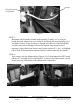
in the chassis of your FX. Guide the FET board into the proper slot in the
chassis and lower it ½ way down. If necessary, plug in the “Thermister” clip to
its connector. Slide the FET board all the way down making sure that the AC
output wires go through the gap on the bottom of the FET board. Bolt down the
FET board and make sure they are tightened to 106 inch pounds.
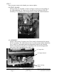
AC ASSEMBLY & CONTROL BOARD: Slide the AC assembly ½ way down
its slot. Connect the AC output wires to the AC assembly starting with the white
wire (on bottom) and then the black wire (on top). With the AC assembly lifted
up as high as possible, insert the Control board in its slot but do not lower it yet.
There is a “Lip” on most of the AC assemblies that fits over the top edge of the
Control board. Some AC assemblies don’t have this feature. If the “Lip” is
present make sure it is over the edge of the Control board. At this point lower
both boards down to the bottom making sure they are in their slots (very
important, check this). Don’t push them down because the AC output wires
may be lodged underneath the AC assembly. With a flashlight, check that the
AC output wires go through the gap provided at the bottom of the AC assembly.
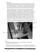
STEP 9:
Once the boards are properly seated and attached, you need to install the ribbon
cables, the AC gasket and the O-rings.
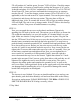
RIBBON CABLES: There are two ribbon cables that are identical but since
they fit into two different spaces they need to be pre-bent in two different ways.
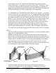
Figure 9 shows the proper bending of the ribbon cable that connects the Control
board to the AC assembly. Figure 10 shows the proper bending of the ribbon
cable that connects the Control board to the FET board. This one is a little
tricky. The ribbon cables have a polarity feature so make sure the notches are in
the correct places. If not, flip the ribbon cable and try again.
Figure 9 Figure 10
Install the ribbon cables between the boards following the connection
instructions in Figures 9 & 10. After making the “Connection to the FET
Notches
Connection to
Control Board
Connection
to FET Board
Connection to
AC Assembly
Bend