FX AND VFX SERIES INVERTER/CHARGER Installation Manual Includes Mounting, Installation, and Product Registration
Warranty Introduction Dear OutBack Customer, Thank you for your purchase of OutBack products. We make every effort to assure our power conversion products will give you long and reliable service for your renewable energy system. As with any manufactured device, repairs might be needed due to damage, inappropriate use, or unintentional defect. Please note the following guidelines regarding warranty service of OutBack products: • Any and all warranty repairs must conform to the terms of the warranty.
TABLE OF CONTENTS Welcome to the OutBack Power Systems FX Series Inverter/Charger System..............................................2 Safety..................................................................................................................................................................................................2 FX Series Inverter/Charger Models............................................................................................................................................
Welcome to the OutBack Power Systems FX Series Inverter/Charger System The FX Series Inverter/Charger offers a complete power conversion system—DC to AC, battery charging, and an AC transfer switch—and can be used as a stand-alone or back-up application. It is designed for indoor or enclosed locations. OutBack Power Systems does everything possible to assure the components you purchase will function properly and safely when installed as instructed according to local and national electrical codes (NEC).
R EA D FIRST! F IR ST ! READ IMPORTANT SAFETY INSTRUCTIONS Read all instructions and cautionary markings on the FX, the batteries and all appropriate sections of this installation and user manual as well as other component manuals before using the system. Be cautious around electricity, electrical components, and batteries. Shocks, burns, injury, and even death can occur if an installer comes in contact with electricity.
WARNING: WORKING NEAR LEAD ACID BATTERIES CAN BE DANGEROUS. BATTERIES GENERATE EXPLOSIVE GASES DURING NORMAL OPERATION. Design the battery enclosure to prevent accumulation and concentration of hydrogen gas in “pockets” at the top of the enclosure. Vent the battery compartment from the highest point to the outside. A sloped lid can also be used to direct the flow of hydrogen to the vent opening.
SYSTEM PROTECTION An FX Series Inverter/Charger is part of an electrical system that protects: • You Each FX must be part of a permanently grounded • The wires electrical system (see page 7). Grounding protects • The components people and equipment from electrical shock. Grounding must be done according to local and • The devices served by the system national electrical codes. OutBack circuit breakers protect wiring by limiting the amount of current entering a system.
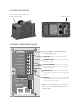
AC WIRING ORIGINATION Lexan cover protects AC Wiring Compartment Board AC Wiring Board AC WIRING COMPARTMENT BOARD AC Terminal Block--secures AC connections to the FX using set screws ���������� • AC HOT OUT supplies power to the loads. �������������� • AC NEUTRAL OUT acts as neutral leg for loads supplied by the FX. ����������������� • CHASSIS GROUND connections are common and act as grounds for both the incoming and outgoing AC circuits.
AC AND DC GROUNDING REQUIREMENTS • Connect only to a grounded, permanent wiring system. Ensure there is only one neutral-ground connection in the system at any time. Some codes require this connection be made at the main panel only. • If the system has a generator, its neutral-ground connection will probably need to be disengaged. • For all installations, the negative battery conductor should be bonded to the grounding system at one (and only one) point in the system.
FX PARTS AND ACCESSORIES TURBO FAN COVER FX-DCC (DC COMPARTMENT COVER) Covers the DC terminal area and provides space to mount other components such as a DC current shunt (can be used with or without the FX-DCA).
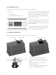
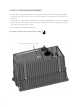
Insert appropriate fasteners at all four corner openings 8.25” 21” Weight is approximately 62 pounds MOUNTING • The FX Series Inverter/Charger is approved for indoor or enclosed protected mounting only. • An FX weighs approximately 62 lbs and must be secured with appropriate fasteners to a sturdy mounting surface capable of supporting its weight. It is easier for two people to install the FX due to its weight.
LOW VOLTAGE TERMINALS ���������� �������������� Note: Keep Control Wiring Terminal Block screws tight and the block itself secured tightly to AC Board. Otherwise, the FX can malfunction. The Terminal Block can be unplugged for easier wire installation and removal/ reinstallation of the FX.
WIRE CONNECTIONS Note: A system’s individual voltage requirements (120 single phase, 120/240 split phase, or 3-phase) as well as how each FX is to function all determine how the FXs are wired. Each FX must be wired to the logical leg or phase of the system. Each FX must be programmed or “stacked” according to this phase. Please see the FX and VFX Series Inverter/Charger Programming Manual before connecting any wires to or from the FX. AC Follow these steps to wire the FX to your system: 1.
TORQUE REQUIREMENTS CONNECTION TORQUE IN POUND MEASURES AC and PV breakers to 22 inch-lbs = 2.48 Nm DC shunt to 15 foot-lbs = 20.4 Nm DC battery connections to 10 foot-lbs = 13.6 Nm FX’s DC Terminals to 10 foot-lbs = 13.6 Nm FX’s AC Terminals to 30 inch-lbs = 3.
AC WIRING NOTES FOR THE NON-MOBILE FX AC HOT OUT • AC hot output conductor (black) wire gauge must be sized to the breakers and loads. ���������� AC NEUTRAL OUT/AC NEUTRAL IN �������������� ����������������� ����������������� CHASSIS GROUND 13 ���� ���� ���� ���� ������ �������� ����� ����� ������ �������� ��� ������������ �������� �� • The AC hot input conductor (black) must be supplied through a 60 amp maximum AC branch rated circuit breaker.
AC WIRING NOTES FOR THE MOBILE FX AC HOT OUT • Supplies the AC hot output conductors through a 30 amp maximum AC branch rated circuit breaker using 6 AWG wire and connect to the AC AC NEUTRAL OUT/AC NEUTRAL IN ���������� • Connects the AC neural input conductor to the AC NEUTRAL IN terminal. • Connects the AC neutral output conductor to the AC NEUTRAL OUT terminal. • Do not assume these terminals are common in the Mobile FX.
LOW-VOLTAGE WIRING This six-position terminal block can be unplugged to make wiring easier and to simplify the removal and reinstallation of an FX. It must be securely and completely plugged in for proper FX functioning. Otherwise, operational errors can occur.
Prior to installing an ON/OFF switch, if the FX’s AC output is off, check that the jumper is present and well-connected before installing a switch. You want to confirm the system is in good working order. Suggested switches include Push On/Push Off Switches (275-671, 275-1555, 275-1565, 275-617, and 275-011) from Radio Shack. Should you decide to install an OutBack MATE at a later date, bear in mind the installed switch overrides the control provided by the MATE if the switch is set to OFF.
RTS, MATE/HUB WIRING ���������� �������������� ����������������� ����������������� RJ-11 modular jack connects RTS, the optional external battery temperature sensor.* ������������� *When a HUB is used, plug the RTS into the Master FX, which should be plugged into HUB’s Port 01. The RTS cable is folded and routed under the AC Wiring Compartment’s Lexan cover, fitting into a small indentation in the aluminum casting between the battery terminals.
SAMPLE INSTALLATIONS SINGLE FX SYSTEM • All non-Mobile FX AC wiring must handle 60 amps AC or more. • A 60A input breaker must be used for a non-Mobile FX and a 30A input breaker for a Mobile FX. • A single FX can continuously power two to three 6KW of loads depending on which model is used.
SERIES OR SERIES/PARALLEL DUAL FX CONFIGURATION • This system can continuously power four 7.2kW of loads depending on which model is used. • All non-Mobile FX AC wiring must handle 60A AC or more. • A Mobile FX requires 30A input breakers. Note: • Stacking FXs in series/parallel means there are FXs directly connected to two separate 120 VAC output legs. These legs produce 240 VAC between them (the series portion). This allows all of the FXs to power either of the 120VAC output legs (the parallel portion).
Series/Parallel Using Two FXs 20
Series/Parallel Using Four FXs 21
PARALLELED DUAL FX SYSTEM • All AC wiring from the AC source and to the AC loads must collectively handle 100 amps AC or more. • All other AC wiring capacity must equal 60 amps AC (Mobile FX units must handle 30 amps AC). • A paralleled dual FX system can continuously power four 7.2kW of loads depending on which model is used.
SERIES/PARALLEL QUAD FX SYSTEM • All AC wiring from the AC source and to the AC loads must collectively handle 120 amps AC or more. • All other AC wiring must handle a capacity of 60 amps AC (Mobile FX AC wiring must handle 30 amps). • This system can continuously power eight 14.4kW of loads depending on which model is used. • Connecting more power than the continuous rating of the FX may cause breakers to trip or the FX to shut off its AC output.
3-PHASE FX SYSTEM • This system produces 120VAC per phase and 208VAC from phase to phase. There can only be one FX per phase on a 3-phase system. • The non-Mobile AC wiring from the AC source and to the AC loads must handle 60 amps AC. • All other non-Mobile AC wiring must handle a capacity of 60 amps AC; Mobile must handle 30 amps AC. • This system can power continuously up to 10.8kW of loads depending on which model is used.
Three-Phase System 25
GENERATOR AUTO START The following schematic shows how to hook up a relay that interfaces with the two-wire start generator. Three-wire start generators require an adapter like the Atkinson GSCM available at www.atkinsonelectronics.com. Most 12V relays will work for generator starting. Select one between 2 and 30 amp contacts.
MOBILE FX INFORMATION When a Mobile system has the option of using either an onboard generator or the utility grid or shore power (see next diagram) as their AC input: • Both the AC “Hot” and AC “Neutral” lines must be connected to the appropriate source. • A connection can be made using a double-pole, double-throw switch (currently unavailable from OutBack, but available from electrical component suppliers) which has one connection each for AC hot and AC neutral.
INSTALLATION CHECK LIST ITEM YES NO All manuals read and reviewed? FX OutBack Charge Controller MATE HUB System mounted with the recommended number and sized fasteners? System installed according to National Electrical Code (NEC) and local codes? System inspected? System permanently grounded? Did the installer use OutBack recommended wire type and gauge adjusted for temperature ratings and length? All AC wiring rated for 75° C or higher? Battery cables rated 75° C or higher? 6 AWG w
APPENDIX RATINGS NOMINAL AC OUTPUT VOLTAGE OF AN FX SYSTEM Single Phase 120 VAC at 60 Hz Series Stacked 120 VAC at 60 Hz per AC output leg / 240 VAC at 60Hz between the AC output legs Parallel Stacked 120 VAC at 60 Hz on one AC output leg Three Phase Stacked 120 VAC at 60 Hz per AC output leg (limit three) / 208 VAC at 60 Hz between AC output legs RECOMMENDED FX DC VOLTAGE RANGE Note: The last two digits in the model number designate the nominal DC voltage. Example: FX2024MT – 24V DC Voltage.
RATED DC INPUT CURRENT Note: This is the maximum continuous DC current that the FX will draw from the batteries when inverting. FX2012(M)T 190 ADC (ADC = Amps DC) FX2524(M)T 95 ADC FX2532(M)T 90 ADC FX3048T 60 ADC VFX2812(M) 265 ADC VFX3524(M) 170 ADC VFX3232(M) 115 ADC VFX3648 85 ADC AC INPUT OPERATING VOLTAGE RANGE Note: This is the recommended AC input voltage range to be supplied to the FX. Voltages outside of this range may damage AC loads connected to the FXs AC output terminals.
MAXIMUM AND DEFAULT AC INPUT AND DC (bulk stage) OUTPUT VALUES FX2012(M)T AC Max = 12 AAC (Default = 10 AAC) DC Max = 100 ADC FX2524(M)T AC Max = 14 AAC (Default = 12 AAC) DC Max = 55 ADC FX2532(M)T AC Max = 14 AAC (Default = 12 AAC) DC Max = 40 ADC FX3048T AC Max = 14 AAC (Default = 12 AAC) DC Max = 35 ADC VFX2812(M) AC Max = 16 AAC (Default = 14 AAC) DC Max = 125 ADC VFX3524(M) AC Max = 20 AAC (Default = 18 AAC) DC Max = 85 ADC VFX3232(M) AC Max = 20 AAC (Default = 18 AAC) DC Max = 60
MAXIMUM OVERCURRENT PROTECTION AMPACITY This rating specifies the proper overcurrent protection ampacity. • • • • • OBDC breakers are panel-mount circuit breakers. Class T DC fuses are terminal-mounted and should always be used in conjuncture with a disconnect mechanism. FXs used in home installations should use properly sized DC circuit breakers. A DC breaker includes both overcurrent protection and disconnect capability.
MAINTENANCE If damaged or malfunctioning, the FX should be repaired by a qualified user, installer, or service center following OutBack Power Systems’ instructions and guidelines. Please contact your energy dealer for assistance. Incorrect repairs and/or reassembly risks malfunction, electric shock or fire. For routine, user-approved maintenance: • Disconnect all circuit breakers and related electrical connections before doing any cleaning or adjustments.
WARRANTY OutBack Power Systems Two Year Limited Warranty OutBack Power Systems Inc. warrants that the products it manufactures will be free from defects in materials and workmanship for a period of two (2) years subject to the conditions set forth below. The limited warranty is extended to the original user and is transferable. The limited warranty term begins on the date of invoice to the original user of the product.
PRODUCT REGISTRATION Your purchase of an OutBack Power Systems product is an important investment. Registering your products will help us maintain the standard of excellence you expect from us in terms of performance, quality and reliability. Please take a moment to register and provide us with some important information.
European Sales Office Barcelona, ESPAÑA (+34) 600.843.845 19009 62nd Avenue NE Arlington, WA 98223 USA (+1) 360.435.6030 www.outbackpower.