
OutBack Power FLEXpower ONE FXR Series Quick Start Guide

Energize/Startup
Procedures
3. Disconnect all AC loads at the backup (or critical) load panel.
4. Disconnect the AC input feed to the FLEXpower ONE at the source.
5. Place the mechanical interlock in the normal (non-bypass) position.
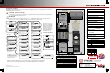
AC Circuit Breakers
DC Circuit Breakers
Side View
Battery
Bank
Mechanical
Interlock
(Bypass)
AC Conduit Box
DC Conduit Box
De-energize/Shutdown
Procedures
WARNING: Lethal Voltage
Review the system configuration to identify all possible
sources of energy. Ensure ALL sources of power are
disconnected before performing any installation or
maintenance on this equipment. Confirm that the
terminals are de-energized using a validated voltmeter
(rated for a minimum 1000 Vac and 1000 Vdc) to verify
the de-energized condition.
WARNING: Lethal Voltage
The numbered steps will remove power from the
inverter and charge controller. However, sources of
energy may still be present inside the GSLC and other
locations. To ensure absolute safety, disconnect ALL
power connections at the source.
WARNING: Burn Hazard
Internal parts can become hot during operation. Do not
remove the cover during operation or touch any internal
parts. Be sure to allow them sufficient time to cool
down before attempting to perform any maintenance.
To de-energize or shut down the OutBack devices:
1. Turnoff(open)theACcircuitbreakers.
2. Turnoff(open)theDCcircuitbreakerforthebattery.
3. Turnoff(open)thePVcircuitbreaker.
4. Turnoff(open)theGFDIcircuitbreaker.
5. Turnoff(open)theFN‐DCcircuitbreaker.
6. *Verify0VdcontheDCinputterminalsoftheinverterby
placingth
evoltmeterleadsonand.
7. *Verify0VdconthePVterminalbyplacingthevoltmeterleads
onand.
8. *Verify0VacontheACoutputcircuitbreakersbyplacingthe
voltmeterleadsintheslotsoftheAC outlet.
Thiscanalsobetestedbyplacingtheleadson
and.
AC Circuit Breakers
DC Circuit Breakers
Side View
Battery
Bank
Mechanical
Interlock
(Bypass)
AC Conduit Box
DC Conduit Box
900-0132-01-01 REV A.vsd
©2013 OutBack Power Technologies. All Rights Reserved.
5
3
*See the Functional Test Points key that is included with the
Startup Procedures.
2
1
2
3
PV Array
PV Array
4
4
GFDI
GFDI
4a 4b
1a 1c
2a 2c
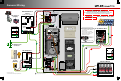
Functional
Test Points
Battery Voltage
Test Points
AC IN Voltage
Test Points
AC OUT Voltage
Test Points
PV Voltage Test Points
3a 3b
4a 3b
1a
1b
1c
Circuit Breaker Terminal
connected to the Battery
Positive (+) Cable
Battery Negative (–)
Terminal on the Inverter
2a
2b
2c
PV Negative (–) Terminal
on the Charge Controller
PV Positive (+) Terminal
on the Charge Controller
Circuit Breaker terminal
for the PV
Circuit Breaker Terminal
connected to the Inverter
DC Positive (+) Cable
1
2
4
1
1
6
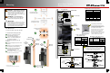
To energize or start up the OutBack devices:
1. Using a digital voltmeter (DVM), verify 12, 24, or 48 Vdc on the DC input
terminals by placing the DVM leads on and . Confirm that the voltage
is correct for the inverter and charge controller models. Confirm the polarity.
2. Verify the voltage on the PV terminal is in the correct range of open-circuit
voltage by placing the DVM leads on and . Confirm the polarity.
3. Connect the AC source. Verify 120 Vac on the AC input circuit breakers by
placing the DVM leads on and .
4. Replace the covers on the AC and DC enclosures.
5. Turn on (close) the GFDI circuit breaker.
6. Turn on (close) the PV input circuit breakers.
7. Turn on (close) the DC circuit breaker from the battery bank to the inverter.
8. Turn on (close) the FN-DC circuit breaker.
9. Check the system display or LED indicators. Ensure the inverter is in the
ON state. The factory default state for FXR inverters is OFF.
10. Turn on (close) the AC output and AC outlet circuit breakers.
11. Verify 120 Vac on the AC output by placing the DVM leads in the slots of the
electrical outlet.
12. Turn on (close) the AC input circuit breakers.
13. Turn on the AC disconnects at the load panel and test the loads.
3
4
6
1
3a 3b
2
1a
1b
2a 2b
CAUTION: Equipment Damage
Incorrect battery polarity will damage the equipment.
5
7
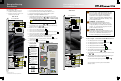
Pre-startup Procedures
After opening the AC and DC enclosures:
1. Double-check all wiring connections.
2. Inspect the enclosure to ensure no tools
or debris has been left inside.
5
6
6
5
3
3b
3a
1a
1b
1c
2b
2a2c
7
5
4a