
OutBack Power FLEXpower ONE FXR Series Quick Start Guide

Wire Sizes/Torque
Requirements
Minimum DC Cable based on the
DC Circuit Breaker
AC Circuit Breakers
GFCI Outlet
DC Circuit Breakers
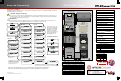
Side View
Battery Bank
Mechanical
Interlock
(Bypass)
Battery
Terminals
AC Conduit Box
DC Conduit Box
Control Wiring Terminal Block:
The Inverter ON/OFF terminals are used for
connecting an external ON/OFF switch. To
use this feature, the jumper must be removed.
(See installation manual for details.)
The AUX terminals provide a 12 Vdc signal.
The AUX terminals can be used to start a
generator or to control external devices.
AUX terminals are also available in the charge
controller and FLEXnet DC. See the charge
controller or FNDC manuals for details.
Torque
In-lb Nm
50 5.6
225 25.4
225 25.4
DC
Circuit
Breaker
Cable Size
125 1/0 (70 mm
2
)
175 2/0 (70 mm
2
)
250 4/0 (120 mm
2
)
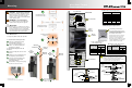
Mounting
To install the mounting bracket:
1. Place the mounting bracket at the
desired height for the panel.
2. Secure the mounting bracket to the
surface. Use all six mounting slots
provided on the bracket.
To mount the FP1 panel on the
bracket:
3. Lift the mounting plate above the wall
bracket.
4. Slip the top of the mounting plate over
the angled lip of the wall bracket.
5. Secure the lower back flange of the
mounting plate to the wall (with
appropriate hardware).
6. Insert all three 1-inch nylon hole plugs
into the rear slot access holes.
WARNING: Fire/Explosion Hazard
Do not place combustible or flammable materials
within 12 feet (3.7 m) of the equipment. This unit
employs mechanical relays and is not ignition-
protected. Fumes or spills from flammable materials
could be ignited by sparks.
WARNING: Personal Injury
Use safe lifting techniques and standard safety
equipment when working with this equipment.
IMPORTANT:
Clearance and access requirements may vary by
location. Maintaining a 36” (91.4 cm) clear space in
front of the system for access is recommended.
Consult local electric code to confirm clearance and
access requirements for the specific location.
Mounting the bracket to
the wall studs 16" apart.
Mounting the bracket to
the wall studs 24" apart.
Mounting the bracket
to plywood
FP1 Dimensions:
33.5" (85 cm) tall X 19.75" (50 cm) wide
1
3
4
FP1
Mounting
Panel
Mounting
Bracket
FP1
Mounting
Plate
Mounting
Bracket
Secure the mounting
plate to the wall at the three
locations. See .
5
2
Wall Stud
Wall Board
Plywood
(if used)
900-0132-01-01 REV A.vsd
©2013 OutBack Power Technologies. All Rights Reserved.
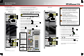
6
1
2
3
4
5
6
Battery
Status
Monitor
PV Array
GFDI
Charge
Controller
AC Terminals
Control
Wiring
Terminals
DC Terminals
CAUTION: Equipment Damage
When connecting cables from the inverter to the battery
terminals, ensure the proper polarity is observed.
Connecting the cables incorrectly can damage or destroy
the equipment and void the product warranty.
Torque requirements for
the conductor lugs
Circuit
Breaker Stud
Torque
In-lb Nm
M8 20 2.3
¼ - 20 35 4.0
5/16 - 18 50 5.6
3/8 - 16 225 25.4
AC Wire Sizes and Torque Values
OutBack recommends that conductors be
#6 AWG THHN copper, or larger, rated to 75°C
(minimum) unless local code requires otherwise.
AWG In-lb
#14 - 10 20
#8 25
#6 - 4 35
#3 35
#2 40
#1 50
1/0 50
mm
2
2.5 – 6
10
16 – 25
35
35
50
70
Nm
2.3
2.8
4.0
4.0
4.5
5.6
5.6
Wire Size Torque
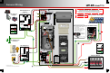
Shunt
*must install upside-down on
units with both Shunt A and
Turbo Kit.
Bolt M8 x 1.25
Lock Washer
Flat Washer
Charge
Controller
Battery (–)
Lug
Inverter
Battery
(–) Lug
Battery Cable Connections
with the FN-DC
Bolt M8 x 1.25
Isolator
Mounting Surface
Inverter Battery
(–) Terminal Post
Inverter
Battery
(–) Lug
Charge
Controller
Battery (–)
Lug
Flat Washer
GFDI
Cable
Lug
Surge
Protector
Cable Lug
Lock Washer
Nut
Battery Cable Connections
without the FN-DC
Nut
Lock Washer
6