TM Mounting Plate User’s Guide Includes Mounting, Installation, and Product Registration
OutBack Power Systems FLEXware is a system of modular aluminum mounting hardware and installation components designed for convenient system installation and integration. About OutBack Power Systems OutBack Power Systems is a leader in advanced energy conversion technology. Our products include true sine wave inverter/chargers, a maximum power point charge controller, system communication components, as well as breaker panels, breakers, accessories, and assembled systems.
Requirements and Warnings The OutBack FLEXware Mounting Plate is listed by ETL to UL standard UL 508A Industrial Control Panels. Grounding Instructions – Any enclosures attached to the FLEXware Mounting Plate should be connected to a grounded, permanent wiring system. For most installations, the negative battery conductor should be bonded to the grounding system at one (and only one) point in the DC system. All installations should comply with all national and local codes and ordinances.
Welcome to OutBack Power Systems’ FLEXware FLEXware is a convenient all-aluminum power system offering simpler, code-compliant installation of OutBack power electronics components.
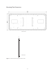
Mounting Plate Dimensions Front View .
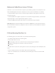
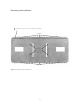
Mounting and Installation T Slot indicates this is the top edge of the FW-MP Lag Bolts Insert hanging screws from back Lag Bolts Figure 2: FLEXware Mounting Plate 5
Installing a Single FLEXware Mounting Plate • The FLEXware Mounting Plate (FW-MP) must be secured to a surface that can safely hold approximately 200 lbs of components and metal hardware; OutBack Power Systems recommends the FW-MP be attached in at least six places with a minimum 2” X ¼” lag bolts/lag screws and flat washers screwed into either wall studs or posts. Most North American construction calls for wall studs to be 16” on center, allowing three available studs in a 32” span for securing the FW-MP.
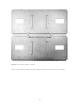
Installing Two FLEXware Mounting Plates • Install the FX Series Inverter/Charger hanging screws (see Figure 2) for each FX used in the system before hanging the FW-MP to a wall. Install the hanging screws from the back of the FW-MP. • Determine the installation location’s upper center point and hammer in a 16d finish nail for the upper mounting slot strip. • Lay both FW-MPs on a flat surface lengthwise against each other and install the hanging straps (included in the FW 1000-AC), connecting the two FW-MPs.
Hanging Straps Figure 3: Two mounting plates installed Please see the FLEXware 500 or FLEXware 1000 installation manuals for system installations.
9
Product Registration Please take a moment to register and provide us with some important information. Send to: OutBack Power Systems, 19009 62nd Avenue NE, Arlington, WA 98223 USA.
19009 62nd Avenue NE Arlington, WA USA (+1) 360-435-6030 European Sales Office Barcelona, España (+34) 600-843-845 www.outbackpower.