
Installation Manual Owner's manual


Installation
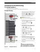
Functional Test/Commissioning
Pre-startup Procedures
1. Double-check all wiring connections.
2. Inspect the enclosure to ensure no tools or debris has been left inside.
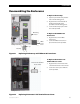
Energize/Startup
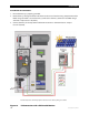
1. Using a digital volt-meter (DVM), verify 24 or
48 Vdc on the Battery terminals (i.e., place
DVM leads on and
in Figure 20).
Confirm that the voltage is correct for the
inverter model. Confirm the polarity.
1-
1+
3
900-0095-01-00 Rev A
33
2. Close the DC Breakers from the battery bank
to the inverter.
2
See Figure 19.
3. Close the AC Output Breakers.
See Figure 19.
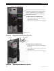
4. Using a digital voltmeter, verify 120 Vac on
the AC Breakers (i.e., place voltmeter leads
on
4+
and
4–
in Figure 20).
5. Close the AC Input Breakers.
5
See Figure 19.
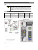
6. Using a digital voltmeter, verify 120 Vac on
the AC Breakers (i.e., place voltmeter leads
on
6+
and
6–
in Figure 20).
7. Close the PV input Breakers.
7
See Figure 19.
8. Using a digital voltmeter, verify the voltage
on the PV terminal does not equal zero
(i.e., place voltmeter leads on
8+
and
8–
in Figure 20).
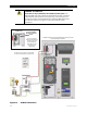
9. Connect a small AC load and test for proper
functionality.
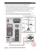
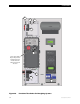
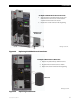
Figure 19 Energize Procedures
2
5
7
CAUTION
: Equipment Damage
A
Incorrect battery polarity wil
l damage the i
nverter.
A
Outlets are model-dependent.
120 V systems will have a 120V outlet,
230 V Systems will have a 230 V outlet.