
Installation Manual Owner's manual
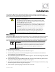

Installation
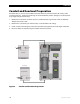
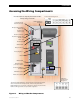
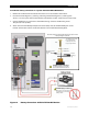
Figure 13 Ground Connections
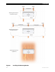
DC Connections
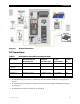
Table 4 DC Conductor Size and Torque Requirements
DC Terminal Minimum Allowed
Conductor Size
Maximum
Conductor Size
Torque
Requirements
Breaker
Size
Battery Positive (+) 2/0 AWG (67.5mm
2
)
N/A (ring terminal) 50 in-lb (5.7 Nm) 175 Adc
Battery Negative (–)
(Shunt)
2/0 AWG (67.5 mm
2
)
N/A (ring terminal) 50 in-lb (5.7 Nm) N/A
PV Positive (+) #4 AWG (21.2 mm
2
)
#2 AWG (33.6 mm
2
) 35 in-lb (4 Nm) 80 Adc
PV Negative (–)
#4 AWG (21.2 mm
2
)
#2 AWG (33.6 mm
2
) 35 in-lb (4 Nm) N/A
Ground Bus Bar #12 AWG (3.3 mm
2
) 1/0 AWG (53.5 mm
2
) 35 in-lb (4 Nm) N/A
To make the battery connections in systems that have the FLEXnet DC Monitor, see Figure 14 on
page 28.
To make the battery connections in sys
tems that do not have
the FLEXnet DC Monitor, see Figure
15 on page 29.
To make the PV connections, see Figure 16 on page 30.
900-0095-01-00 Rev A
27