
Installation Manual Owner's manual

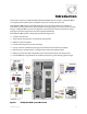
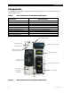
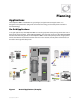
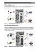
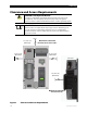

Table of Contents
10 900-0095-01-00 Rev A
List of Figures
Figure 1 FLEXpower ONE System Overview............................................................................................................................11
Figure 2 Basic Components of a FLEXpower ONE System..................................................................................................12
Figure 3 On-Grid Applications (Example).................................................................................................................................13
Figure 4 Off-Grid Applications (Example).................................................................................................................................14
Figure 5 Grid-Interactive Applications (Example)..................................................................................................................14
Figure 6 Clearance and Access Requirements ........................................................................................................................18
Figure 7 Dimensions........................................................................................................................................................................19
Figure 8 Conduit and Knockout Preparation...........................................................................................................................20
Figure 9 Installing the Mounting Bracket .................................................................................................................................22
Figure 10 Attaching the Mounting Plate to the Mounting Bracket ...................................................................................23
Figure 11 Removing the Covers .....................................................................................................................................................24
Figure 12 Wiring and Breaker Compartment.............................................................................................................................25
Figure 13 Ground Connections ......................................................................................................................................................27
Figure 14 Battery Connections with the FLEXnet DC Monitor.............................................................................................28
Figure 15 Battery Connections without the FLEXnet DC.......................................................................................................29
Figure 16 PV Connections with a FLEXnet DC Monitor..........................................................................................................30
Figure 17 AC IN Connections...........................................................................................................................................................31
Figure 18 AC OUT Connections......................................................................................................................................................32
Figure 19 Energize Procedures.......................................................................................................................................................33
Figure 20 Functional Test Procedures for Initial Startup........................................................................................................34
Figure 21 Replacing the Raceway and FLEXmax 80 Front Cover........................................................................................35
Figure 22 Replacing the Inverter’s AC Terminal Access Cover.............................................................................................35
Figure 23 Replacing the AC Enclosure Front Cover.................................................................................................................36
Figure 24 Replacing the AC Enclosure Top Cover....................................................................................................................36
Figure 25 Replacing the DC Enclosure Front Cover.................................................................................................................37
Figure 26 Replacing the DC Cover.................................................................................................................................................37
Figure 27 MATE2 Setup Screen (Page 1) .....................................................................................................................................40
Figure 28 MATE2 Setup Screen (Page 2 and 3) .........................................................................................................................41
Figure 29 Inverter Setup Screen – Selecting AC Source.........................................................................................................42
Figure 30 Accessing the Advanced Menus.................................................................................................................................43
Figure 31 Setting Battery Amp-hours and Return Amps.......................................................................................................44
Figure 32 Setting Input Source and Current Limit...................................................................................................................45
Figure 33 Shutdown Procedures....................................................................................................................................................46
Figure 34 Functional Test Procedures to Confirm the Unit is De-energized...................................................................47
Figure 35 FLEXpower ONE with FLEXnet DC Monitor and GFDI.........................................................................................61
Figure 36 FLEXpower ONE with FLEXnet DC Monitor Only (No GFDI)..............................................................................62
Figure 37 FLEXpower ONE with GFDI Only (no FLEXnet DC Monitor) ..............................................................................63
Figure 38 FLEXpower ONE (no FLEXnet DC Monitor or GFDI) .............................................................................................64