power ONE TM Installation Manual
About OutBack Power Systems OutBack Power Systems is a leader in advanced energy conversion technology. Our products include true sine wave inverter/chargers, maximum power point charge controllers, system communication components, as well as breaker panels, breakers, accessories, and assembled systems. Contact Information Telephone: Address: E-mail: Web Site: +1.360.435.6030 (North America) +1.360.618.4363 (Technical Support) +1.360.435.6019 (Fax) +34.93.654.
Important Safety Instructions READ AND SAVE THESE INSTRUCTIONS! This manual contains important safety instructions for the FLEXpower ONE. Read all instructions and cautionary markings on the FLEXpower ONE and on any accessories or additional equipment included in the installation. Failure to adhere to these instructions could result in severe shock or possible electrocution. Exercise extreme caution at all times to prevent accidents.
Important Safety Instructions Definitions Off-Grid – Utility Grid Power is not available for use. On-Grid – Utility Grid power is available for use. Does not imply the ability to sell power back to the utility grid. Grid-tie, Grid-interactive, Grid-intertie – Utility Grid Power is available for use and the system is capable of returning (selling) electricity back to the utility grid.
Important Safety Instructions Personal Safety WARNING: Personal Injury This equipment weighs approximately 98 lbs (44.5 kg). Use safe lifting techniques when lifting this equipment as prescribed by the Occupational Safety and Health Association (OSHA) or other local codes. Use standard safety equipment such as safety glasses, ear protection, steeltoed safety boots, safety hard hats, etc.
Important Safety Instructions CAUTION: Equipment Damage When connecting cables from the inverter to the battery terminals, ensure the proper polarity is observed. Connecting the cables incorrectly can damage or destroy the equipment. Thoroughly inspect the equipment prior to energizing. Verify that no tools or equipment have been inadvertently left behind.
Important Safety Instructions WARNING: Fire or Burn Hazard Ensure the cables are properly sized. Failure to size the cables properly can result in a Fire Hazard. Wear complete eye protection and clothing protection when working with batteries. Avoid touching your eyes while working near batteries. If battery acid contacts skin or clothing, wash immediately with soap and water.
Important Safety Instructions Earth 911 Web site: Address: Phone: www.Earth911.com 14646 N. Kierland Blvd., Suite 100 Scottsdale, AZ 85254 +1.480.337.3025 (direct) Environmental Protection Agency, USA Web site: Phone: Email: www.epa.gov/recyclecity/ +1.415.947.8000 (Monday –Friday 8:00 AM to 12:00 PM and 1:00 PM to 4:00 PM PST) r9.recyclecity@epa.gov Keep America Beautiful, USA Web site: Address: Phone: Fax: Email: www.kab.org/ 1010 Washington Boulevard Stamford, CT 06901 +1.203.659.
Table of Contents Important Safety Instructions ...................................................................1 Symbols Used ........................................................................................................................................................................1 Audience .................................................................................................................................................................................1 Definitions.............
Table of Contents AC Connections ..............................................................................................................................................................................31 Functional Test/Commissioning.................................................................................................................................. 33 Pre-startup Procedures ...................................................................................................................
Table of Contents List of Tables Table 1 Table 2 Table 3 Table 4 Table 5 Table 6 Table 7 Table 8 Acronyms.............................................................................................................................................................................. 2 Basic Components of a FLEXpower ONE System..................................................................................................12 Ground Conductor Size and Torque Requirements........................................
Table of Contents List of Figures Figure 1 Figure 2 Figure 3 Figure 4 Figure 5 Figure 6 Figure 7 Figure 8 Figure 9 Figure 10 Figure 11 Figure 12 Figure 13 Figure 14 Figure 15 Figure 16 Figure 17 Figure 18 Figure 19 Figure 20 Figure 21 Figure 22 Figure 23 Figure 24 Figure 25 Figure 26 Figure 27 Figure 28 Figure 29 Figure 30 Figure 31 Figure 32 Figure 33 Figure 34 Figure 35 Figure 36 Figure 37 Figure 38 10 FLEXpower ONE System Overview .......................................................................
Introduction Thank you for choosing a FLEXpower ONE System from OutBack Power Systems. FLEXpower ONE is an integrated power system solution designed to be quick to install and easy to use. The FLEXpower ONE System is intended for off-grid and on-grid applications up to 3.6 kW. It is intended for use with photovoltaic (PV) modules for harvesting energy and a battery bank for energy storage.
Introduction Components A complete FLEXpower ONE is composed of the following components. See page 49 for details on specific configurations.
Planning Applications The FLEXpower ONE is intended for on-grid, off-grid, and grid-interactive applications. It is designed to use photovoltaic (PV) panels to harvest solar energy and a battery bank to store the harvested energy. On-Grid Applications In on-grid applications, the FLEXpower ONE can use the grid power as the primary power source or as the backup source of power. If the FLEXpower ONE is used as backup to the grid, the FLEXpower ONE will take over when the grid fails.
Planning Off-Grid Applications In off-grid applications, the FLEXpower ONE can use the harvested energy from the battery bank as the primary power source. An AC generator can also be connected to support the system when required. Figure 4 Off-Grid Applications (Example) Grid-Interactive Applications In grid-interactive applications, grid power is used to run the loads. When excess PV is available from the batteries, the FLEXpower ONE supports those loads with the PV.
Planning PV Array Planning The FLEXpower ONE is designed to use PV input to charge the battery bank. The FLEXmax 80 charge controller(s) integrated into the FLEXpower ONE System uses Maximum Power Point Tracking (MPPT) technology to maximize the PV harvest. A PV Combiner box (not included) may be required for multiple PV strings. PV Combiner Boxes are available from OutBack Power Systems for 8 to 12 PV strings. FLEXpower ONE includes one FLEXmax 80 Charge Controller.
Planning Generator Requirements IMPORTANT: All connections must comply with local electric code. Generator grounding and neutral-to-ground bonding should be provided in accordance with specific system configuration and national/local code requirements. Follow the manufacturer’s recommendations for fuel type and maintenance. The following are general requirements for using a generator with the FLEXpower ONE.
Planning Preparation Tools Required The following tools may be required for installing this equipment. Wire cutters/strippers Torque wrenches Assorted insulated screw-drivers Drill and drill-bits Ratchet drives Digital Voltmeter Materials Required The following materials may be required for installing this equipment.
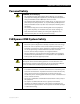
Planning Clearance and Access Requirements WARNING: Fire/Explosion Hazard Do not place combustible or flammable materials within 12 feet (3.7 m) of the equipment. This unit employs mechanical relays and is not ignitionprotected. Fumes or spills from flammable materials could be ignited by sparks. IMPORTANT: Clearance and access requirements may vary by location. Maintaining a 36” (0.91 cm) clear space in front of the system for access is recommended.
Planning Dimensions 19¾” (481 cm) 16” (41 cm) Mounting Bracket ≈13” (33 cm) 33½” (851 cm) Side View Figure 7 900-0095-01-00 Rev A Dimensions 19
Planning Conduit and Knockout Preparation Knockouts (two 1”, one 2”) are provided on the ends of the AC and DC enclosures for routing cable into the enclosures. Conduit and bushings are recommended to prevent damage to conductors from sharp edges along knockout holes. 1. Remove the 2” knockout on the DC end to accommodate the larger battery cables and Remote Temperature Sensor cable. 2. Remove the 1” knockout(s) on the AC end to accommodate the AC cabling. 3.
Installation The FLEXpower ONE system is designed for flexibility and easy installation. The system comes attached to a mounting plate with the selected components pre-installed and wired. The Mounting Plate attaches to a mounting bracket that attaches to a wall. WARNING: Personal Injury This equipment weighs 98 lbs (44.5 kg). Use safe lifting techniques when lifting this equipment as prescribed by the Occupational Safety and Health Association (OSHA) or other local codes.
Installation Mounting the bracket to wall studs 16” apart. Mounting the bracket to wall studs 24” apart. Mounting the bracket to plywood.
Installation Lift the Mounting Plate above the wall bracket. Slip the top of the Mounting Plate over the angled lip of the wall bracket. Secure the Mounting Plate to the wall at the 3 locations shown below. Secure the Mounting Plate to the wall at the 3 locations shown here.
Installation Removing the Covers Remove the screws in the AC Enclosure’s Front Cover (x4). Gently pull the Front Cover away from the chassis being careful not to disconnect or damage the wiring for the Surge Protector. The Front Cover cannot be completely removed due to the Surge Protector wiring (see page 52). Remove the screws on the AC Access Cover (x2). Note: The AC Enclosure has two covers: the access cover and the front cover. Both covers need to be opened to make conductor connections.
Installation Accessing the Wiring Compartments Internal components may vary from model to model. Factory wiring is not shown.
Installation Wiring IMPORTANT: All connections must comply with local electric code. Local code may require sizes other than those recommended in this manual. For all wiring, use copper conductors rated at 75°C minimum.
Installation Figure 13 Ground Connections DC Connections Table 4 DC Conductor Size and Torque Requirements DC Terminal Minimum Allowed Conductor Size Maximum Conductor Size Torque Requirements Breaker Size Battery Positive (+) 2/0 AWG (67.5mm2) N/A (ring terminal) 50 in-lb (5.7 Nm) 175 Adc Battery Negative (–) (Shunt) PV Positive (+) 2/0 AWG (67.5 mm2) N/A (ring terminal) 50 in-lb (5.7 Nm) N/A #4 AWG (21.2 mm2) #2 AWG (33.6 mm2) 35 in-lb (4 Nm) 80 Adc PV Negative (–) #4 AWG (21.
Installation To make the battery connections in a system with the FLEXnet DC Monitor: 1. Remove all hardware from the side of Shunt A that is not connected to the Inverter. 2. Place the Inverter Negative (–) cable lug and Charge Controller Negative (–) cable lug onto Shunt A. Secure in place with the Flat Washer, Lock Washer and Nut. Torque to 50 in-lb (5.7 Nm). 3. Connect the Battery (+) conductor to the DC Breaker lug closest to the Mounting Panel. Torque to 50 in-lb (5.7 Nm). 4.
Installation To make the battery connections in a system without the FLEXnet DC Monitor: 1. Remove all hardware from the inverter’s battery negative (–) terminal post. 2. Place the Inverter Negative (–) cable lug and Charge Controller Negative (–) lug onto the terminal post. Secure in place with the Flat Washer, Lock Washer and Nut. Torque to 50 in-lb (5.7 Nm). 3. Place the GFDI cable lug and Surge Protector DC Negative (–) cable lug onto the terminal post. Secure in place with the next Lock Washer and Nut.
Installation To make the PV connections: 1. Ensure the PV array is properly grounded. 2. Route the PV (–) through the bottom of the DC enclosure and into the wiring compartment of the FM80 charge controller. Connect the PV (–) conductor to the PV (–) terminal in the FM80 charge controller. Torque to 35 in-lb (4 Nm). 3. Connect the PV (+) to the top terminal of the PV Disconnect in the DC Enclosure. Torque to 35 in-lb (4 Nm). Internal components shown may vary from model to model.
Installation AC Connections WARNING: Fire Hazard Multi-wire branch circuits in residential installations can create a potential fire hazard with inverter installations. Be sure to check for multi-wire branch circuits before making any AC connections and make any changes required to remove the hazard. Table 5 AC Conductor Size and Torque Requirements AC Terminal Minimum Allowed Conductor Size Maximum Conductor Size Torque Requirements Breaker Size AC IN AC OUT Neutral Bus Bar #14 AWG (2.
Installation WARNING: Shock Hazard Ensure there is only one Neutral-to-Ground Bond in the system. The FLEXpower ONE comes with a Neutral-to-Ground Bond installed. If a Neutralto-Ground bond exists elsewhere in the system (e.g., in the main panel, or a generator), the Neutral-to-Ground Bond in the FLEXpower ONE AC Enclosure will need to be removed. See Figure 18. Check local code for specific requirements.
Installation Functional Test/Commissioning Pre-startup Procedures 1. Double-check all wiring connections. 2. Inspect the enclosure to ensure no tools or debris has been left inside. Energize/Startup Using a digital volt-meter (DVM), verify 24 or 48 Vdc on the Battery terminals (i.e., place 1. DVM leads on 1+ and 1- in Figure 20). Confirm that the voltage is correct for the inverter model. Confirm the polarity. 3 5 CAUTION: Equipment Damage Incorrect battery polarity will damage the inverter.
Installation 4+ 4– 6– 6+ 1– Note: The shunt may or may not be installed on your model. Use the same test point in all cases.
Installation Reassembling the Enclosures To Replace the Raceway: Mounting Panel Slot 1. Slip the lip on the Raceway into the slot on the mounting panel. 2. Align the holes on the bottom of the Raceway with the holes provided on the mounting panel. 3. Secure the Raceway in place with the screws provided. To Replace the FLEXmax 80 Front Cover: 1. FM80 Front Cover Cabling not shown. 2. Align the holes on the FM80 Front Cover. Secure the FM80 Front Cover in place with the screws provided.
Installation The Front Cover of the AC Enclosure will not be completely removed due to the surge protector cabling. Work with care not to damage the surge protector or dislodge the cabling as you replace the Front Cover. To Replace the Front of AC Enclosure: 1. Align the holes (x4) in the enclosure front cover with the holes in the chassis. 2. Replace the screws (x4) removed in the beginning. Cabling not shown.
Installation To Replace the DC Enclosure Front Cover: 1. Align the holes in the DC Enclosure Front cover with the holes in the chassis. Ensure that the “lip” fits into the notch in the chassis. 2. Replace the screws removed in the beginning. DC Enclosure Front Cover Notch Cabling not shown. Lip Figure 25 Replacing the DC Enclosure Front Cover To Replace the Inverter’s DC Cover: 1. Replace the plastic Battery Terminal Covers. 2. Align the holes in the DC Cover as shown. 3.
Installation 38 900-0095-01-00 Rev A
Operation Setting Basic Parameters IMPORTANT: This section assumes that the operator is familiar with the basic operation and navigation of the installed components. Detailed information about component settings is provided in each of the components respective manuals. Although some of the programming will be pre-set at the factory (i.e.
Operation Setting Time, Date & Display on the MATE2 IMPORTANT: The following information assumes the installer is familiar with the basic operation of a MATE2 System Controller and Display. If the installer is not familiar with basic operation, please refer to the MATE Installation and User Manual for general information.
Operation Continued from page 40.
Operation Selecting the AC Source and AC Input Limit on the Inverter AC1 GRID Menu: Adjusts the maximum current the inverter will draw from the grid for either supporting loads or battery charging (between 5.0 Aac and 60.0 Aac). AC2 GEN Menu: Adjusts the maximum current the inverter will draw from the generator for either supporting loads or battery charging (between 2.0 Aac and 60.0 Aac). INC: Pressing this soft key increases the value. DEC: Pressing this soft key decreases the value.
Operation Accessing the Advanced Menu In most cases, the charging parameters set at the factory will work for most systems. However, if changes are required, these parameters are set using the Advanced Menu system. This includes the charging input current limit and the voltage and time limit for each stage of charging. IMPORTANT: Making changes to the Advanced Settings could adversely affect current system performance. Only make changes to the factory default settings if you are qualified to do so.
Operation Setting Battery Amp-Hours and Return Amps using the FLEXnet DC Monitor If a FLEXnet DC Monitor is installed in the configuration, the following parameters will need to be set. Battery Amp-Hours refers to the total amp-hour capacity of the battery bank (not just amp-hour rating of the individual batteries within the battery bank). Return Amps is the low limit to which an absorption current must decrease, while still maintaining the absorption voltage, before the battery is judged to be full.
Operation Setting Charging Parameters If changes need to be made to charging parameters, follow the menu map below. IMPORTANT: Access the Advanced Menu as instructed on page 43. To Set Charging Limits: 1. Press the Soft Key. 2. Press the or Soft Key to change the parameter. 3. Press to advance to the next parameter. 4. Continue pressing to cycle through all the settings. IMPORTANT: Consult the Battery Manufacturer for exact charging requirements.
Operation De-energize/Shutdown WARNING: Lethal Voltage Review the system configuration to identify all possible sources of energy. Ensure ALL sources of power are disconnected before performing any installation or maintenance on this equipment. Confirm that the terminals are de-energized using a validated voltmeter (rated for a minimum 1000 Vac and 1000 Vdc) to verify the de-energized condition. WARNING: Burn Hazard Internal parts can become hot during operation.
Operation 6– 6+ Note: The shunt may or may not be installed on your model. Use the same test point in all cases.
Operation 48 900-0095-01-00 Rev A
Specifications Feature Matrix The following Matrix shows the FLEXpower ONE models that are described in this manual.
Specifications Electrical Specifications, 120 Vac/60 Hz Models Product Name FP1-1 VFX3524 Inverter Model FP1-2 FP1-3 FP1-4 VFX3648 GVFX3524 GVFX3648 Grid-Interactive No No Yes Yes Anti-Islanding Protection N/A N/A UL1741-2005/ IEEE1547 UL1741-2005/ IEEE1547 Total Harmonic Distortion Sell Current N/A N/A < 5% < 5% Invert Voltage N/A N/A 2% Typical 2% Typical Output Waveform Battery Voltage True Sine Wave Nominal Operating Range Recommended Minimum Battery Capacity 24 Vdc 48
Specifications Electrical Specifications, 230 Vac/50 Hz Models Product Name FP1-5 FP1-6 VFX3024E Inverter Model Output Waveform Battery Voltage VFX3048E True Sine Wave Nominal Operating Range Recommended Minimum Battery Capacity 24 Vdc 48 Vdc 20-30 Vdc 40-60 Vdc 200 Amp-hours 100 Amp-hours For Models with FM80 Charge Controller: Maximum PV Array Wattage 2000 WdcSTC 4000 WdcSTC PV Input Voltage Range 25-150 VOC 50-150 VOC PV Operating Voltage Range 25-145 Vdc 50-145 Vdc PV Maximum Op
Specifications Surge Protector The FLEXware Surge Protector is designed to protect the FLEXpower ONE’s sensitive components from excessively high voltages (e.g., electrical storms). Thermally-fused metal oxide varistors (MOVs) limit (“clamp”) these voltages and transfer the resulting current to a lower-voltage port. The FLEXware Surge Protector features ACTIVE and ERROR LEDs for the DC, AC IN, and AC OUT circuits. The Surge Protector is located in the FLEXpower ONE’s AC wiring compartment.
Specifications Renewable Energy Input & Storage PV Sizing Single charge control systems can support photovoltaic arrays with the following specifications. Dual charge controller systems can handle 2 arrays with the following specifications. Maximum Array Size 4,000 WSTC on 48 Vdc system, 2,000 WSTC on 24dc system 145 Vdc (150 VOC including local temperature correction factor per NEC 690.7) 64 A ISC maximum PV array current per NEC 690.
Specifications Discharge Rate Deep cycle batteries express the amp-hour rating as "at the x-hour rate". This is an average rate of current flow that would take x number of hours to discharge the batteries. Common amp-hour figures are at the 6-hour rate, the 20-hour rate, and the 100-hour rate. A battery is classified as having fewer amp hours if it is discharged at a faster rate, such as the 6-hour rate. There is an inevitable amount of heat associated with the flow of current through a battery.
Specifications Refrigerators and ice-makers typically run only about 1/3 of the time, therefore, the running wattage is 1/3 of the total wattage of the appliance. Divide the total wattage of the appliance by 3 when determining the battery requirements. Calculating Amp-Hours To determine the amp-hours that will be consumed, list the anticipated loads and the length of time they will operate. Use the specifications noted on the labels of each AC load that is to be connected to the system.
Specifications Worksheet for Calculating Amp-hour Requirements Use the following worksheet to calculate the amp-hour requirements.
Specifications Worksheet for Calculating Battery Bank Size Use the following worksheet to calculate the battery bank size. Table 8 Worksheet for Determining Battery Bank Size Average amp-hours per day (from Table 7) Divided by inverter efficiency Divided by battery efficiency (usually 0.
Specifications This page intentionally left blank.
Wiring Configurations The following wiring configurations are provided as examples only. Actual wiring requirements may vary depending on local electric code. All installations must comply with local electric code.
Wiring Configurations This page intentionally left blank.
900-0095-01-00 Rev A Figure 35 FLEXpower ONE with FLEXnet DC Monitor and GFDI FLEXpower ONE with FLEXnet DC Monitor and GFDI 61 Wiring Configurations
62 Figure 36 FLEXpower ONE with FLEXnet DC Monitor Only (No GFDI) FLEXpower ONE with FLEXnet DC Monitor Only (no GFDI) 900-0095-01-00 Rev A Wiring Configurations
900-0095-01-00 Rev A Figure 37 FLEXpower ONE with GFDI Only (no FLEXnet DC Monitor) FLEXpower ONE with GFDI Only (no FLEXnet DC Monitor) 63 Wiring Configurations
64 Figure 38 FLEXpower ONE (no FLEXnet DC Monitor or GFDI) FLEXpower ONE (no FLEXnet DC Monitor or GFDI) 900-0095-01-00 Rev A Wiring Configurations
Warranty 5-Year Limited Warranty for FLEXpower ONE Products OutBack Power Systems, Inc. (“OutBack”) provides a five-year (5) limited warranty (“Warranty”) against defects in materials and workmanship for its FLEXpower ONE products (“Product”) if installed in fixed location applications within the United States and Canada. The term of this Warranty begins on the Product(s) date of manufacture or the initial purchase date as indicated on the warranty registration card submitted to OutBack, whichever is later.
Warranty Information How to Arrange for Warranty Service During the warranty period beginning on the invoice date, OutBack Power Systems will repair or replace products covered under this limited warranty that are returned to OutBack Power Systems’ facility or to an OutBack Power Systems authorized repair facility, or that are repaired on site by an OutBack Power Systems authorized repair technician. IMPORTANT: For full Warranty description, see page 65.
Index A E AC Conductor Size and Torque Requirements ............. 33 AC Connections ................................................................................ 34 Access Requirements .................................................................... 18 Accessing the Advanced Menus............................................ 46 Accessories........................................................................................... 17 Advanced Menu ......................................................
Warranty Information Planning............................................................................................... 13 Preparation........................................................................................... 17 Pre-startup Procedures................................................................. 35 PV Connections................................................................................. 32 PV Planning.............................................................................
Thank you for supporting OutBack Power Systems by installing this product. Your patronage is greatly appreciated. This product was proudly assembled in the United States of America and demonstrates the quality and pride of this great team of employees. We sincerely hope your experience has been pleasant, positive, and professional and hope that you’ll consider OutBack Power Systems for future purchases.
North America 19009 62nd Avenue NE Arlington, WA USA 1.360.435.6030 European Office: Barcelona, España 34.93.654.