OUTBACK STM OWNER’S MANUAL December, 2005 DOM-OBK01 Rev.
Congratulations on your purchase of an Outback STM Introduction . . . . . . . . . . . . . . . . . . . . . . . . . . . . . . . .1 Installation . . . . . . . . . . . . . . . . . . . . . . . . . . . . . . . . .2 Power Up . . . . . . . . . . . . . . . . . . . . . . . . . . . . . . . . . .5 Setup . . . . . . . . . . . . . . . . . . . . . . . . . . . . . . . . . . . . .5 Correction Types . . . . . . . . . . . . . . . . . . . . . . . . . . . .6 Contour Guidance . . . . . . . . . . . . . . . . . . . . . . . . . .
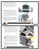
. Determine Display Location: Normally, the display is located above and behind the center of the steering wheel just below the driver's line of sight. The easiest installation is on the front glass of the cab. If that's not possible, it can vacuum mount to any non porous (metal) surface or the vacuum mount can be removed and the bracket mounted with bolts. 4. Mount Display Unit: THOROUGHLY clean the inside cab window surface directly in front of the steering wheel.
POWER UP SETUP 1. Turn Unit On, After Starting Engine: Toggle the power switch located on the right end of the display. The RED status light will illuminate. Using the Menu: To access the menu, press the MENU button. Choose the item you want using the up and down arrow keys. The > character points to the active menu item. Press ENTER to select. 1. EDRIVE SETUP: Optional menu item appears only if eDrive® is installed. See the Outback eDrive® owner’s manual for details. Power Switch 2.
4. Making A New First Pass: Let's say you've made several passes and then want to start a new line that doesn't follow the last one. Simply drive where you want to go. Once it becomes obvious that you're not guiding from another pass, the unit will go back into logging pass mode. CONTOUR GUIDANCE 1. Background: Choose contour guidance whenever you want to follow previous passes. In this mode, you are either logging an initial pass or guiding from a previous pass.
4. Switching Modes: You may switch between straight and contour modes at will. When switching to straight mode for the second time, you are given the option of using the previous A=B line or setting a new one. HEADLAND PRESENCE The headland presence indicators display anytime that the antenna crosses into a previously applied area. This feature may be turned on or off from the setup menu. Headland Indicators 5.
CONTOUR & STRAIGHT GUIDANCE SUMMARY Item CONTOUR MODE STRAIGHT MODE Mode of Operation Work Recorded In Memory Freestyle. Guide relative to any previous pass. Yes. In fact, the recorded pass defines where the next pass will be guided. Predefined straight parallel and numbered passes. Yes. Although, recorded work in straight mode is not used for guidance, it would be used if the operator switches to contour mode and then wishes to make A=B Points required No. Guidance is based on previous passes.
Stop Guidance and Resuming at a Future Time: Any time the operator needs to suspend field application, whether for an hour or days, the following procedure will allow guidance to be resumed without interruption. USING e-DifTM CORRECTION The patented e-Dif™ correction method uses only the standard GPS satellites and does not require an external correction signal of any type. It works by analyzing the error trends from the GPS satellites and projects new correction values into the future.
DIAGNOSTICS This section provides helpful information for operating or troubleshooting the unit. Item SATS: TRK=00 USE IN CALC=00 CORRECTION TYPE DIFF AGE BIT ERROR RATE MEMORY GPS SOFTWARE VER APP SOFTWARE VER SERIAL NUMBER LED TEST POSITION Description Tells the number of satellites currently visible in the sky. This is only GPS satellites and does not include the correction satellites. Displays the type of differential correction being used. There are two types loaded into the receiver.
and exterior housing. If you measure ±5 VDC at the console connector, but not at the end of the coaxial cable, then the cable is damaged. Replace the coaxial cable and return to step 1. 9. If you do not measure ±5 VDC from your Outback console, contact Outback Customer Service to return the console for servicing. SECTION 1 - TESTING ANTENNA VOLTAGE The Outback antenna is an "Active" antenna that requires power to operate.
lel in Canada. WAAS is not available currently anywhere else in the world. For more information about WAAS contact the FAA at http://gps.faa.gov/Programs/WAAS/waas.htm. FREQUENTLY ASKED QUESTIONS ABOUT GPS GUIDANCE Q: What is GPS? A: GPS stands for Global Positioning System. It's a satellite based signal operated by the Department of Defense and is available to anyone to provide position information to receivers on the ground.
A: To erase the memory in the Outback STM, first press the STOP GUIDANCE button. Next, press the down arrow to place the pointer next to ERASE MEMORY. If ERASE MEMORY does not appear, simply press the down arrow until it does. Finally, press the enter button to select the function. Q: How do I perform headlands? A: This is very easy. Usually headlands are performed in contour mode. Make one pass and then use the guide on the second pass. Do this wherever turning will be done.
CONTACTING THE FACTORY U.S: Outback Guidance Hemisphere GPS, L.L.C. 2005 West Oregon Street P.O. Box 238 Hiawatha, KS 66434 USA E-MAIL: 24 hours / 7 days a week, your inquiry will receive a response from one of our Customer Support Representatives within one business day. Sales: outbacksales@outbackguidance.com Customer Service: outbackcs@outbackguidance.com Website Feedback: outbackweb@outbackguidance.com Canada: Outback Canada Hemisphere GPS, L.L.C.
LIMITED OUTBACK STM ONE-YEAR WARRANTY parts added to an Outback S™ system after the system is shipped from OUTBACK, accessories or parts that are not installed in the OUTBACK factory. Hemisphere GPS, L.L.C. ("OUTBACK") manufactures its hardware products from parts and components that are in accordance with industry standard practices. OUTBACK warrants that the hardware products it manufactures will be free from defects in materials and workmanship.
authorized by OUTBACK, usage not in accordance with product instructions, failure to perform required preventive maintenance and problems caused by use of parts and components not supplied by OUTBACK.
PARTS LISTING Outback STM Guidance System REF. 1 2 3 4 5 6 P/N AB443 60054 60055 TS-7R DESCRIPTION Antenna Assembly, see page 31 Plate, Antenna Mounting w/Double Sided Tape Antenna Cable, OBK-S - 20ft Lg Console Assembly, see page 30 Power Cable, OBK-S - 15ft Lg, Cig Lighter Plug Tie Strap, 7" - Releasable QTY. 1 1 1 6 29 Console Mounting Details REF.
Antenna Mounting Details REF. 1 2 P/N AB444 60052 60085 DESCRIPTION Antenna, OBK-S w/Labels - Replacement Antenna, Mounting Kit - Generic Magnet, Antenna Mount - Replacement 31 NOTES 32 QTY.
Outback Guidance Supplemental Instructions for Version 4.06 Software ALTERNATE DISPLAY SCREENS While operating in contour or straight guidance modes, the up and down arrow keys will present alternate display screens. Repeated pressing of the down arrow will display the following screens. 0. Normal Guidance Screen 1. Perimeter Area / A=B Line Adjustment Screen 2. Ground Speed and Heading Screen 3.