
User Manual
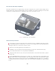
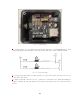
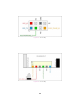

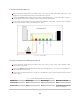
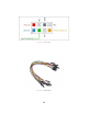

Table Of Contents

Connection using the GPS Port
Connect the PPS output from your GPS to the sync_pulse_in pin of the GPS connector to be
plugged on the Ouster Interface Box, pictured below in yellow.
Connect the NMEA UART output from your GPS to the multipurpose_io pin of the GPS connector
to be plugged on the Ouster Interface Box, pictured below in magenta.
Connect the ground output from your GPS to the GND pin of the GPS connector to be plugged
on the Ouster Interface Box, pictured below in gray.
Figure8.1: J2 Circuitry
Connection using the Pin out 4x2 pin header J7
Connect the PPS output from your GPS to the sync_pulse_in pin of the Ouster Interface Box,
pictured below in yellow.
Connect the NMEA UART output from your GPS to the multipurpose_io pin of the Ouster Interface
Box, pictured below in green.
Connect the ground output from your GPS to the GND pin of the Ouster Interface Box, pictured
below in gray.
Table8.1: SYNC_PULSE_IN Interface Requirements
Parameter Min Voltage Max Voltage Min Driver Current
LOGIC LOW -30 V 2 V N/A
LOGIC HIGH 2.9 V 30 V 3mA @3.3V~5V, 5mA
at 24V and higher
27