
User Manual
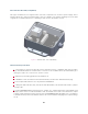
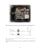
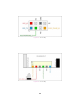

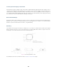
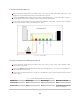
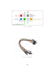

Table Of Contents

Figure7.2: Components
7 - 3.3kω pullups to VCC_3P3|5 and green LED indicators for MULTIPURPOSE_IO and
SYNC_PULSE_IN. Install a jumper on the respective header (J8 or J9) to enable the pullup.
Figure7.3: J8 & J9 Circuitry
8 - 0.1” pitch, 4x2 pin header J7. GPS_TX (Pin 1) is only connected to connector J2; it is not
connected to the sensor.
9 - 6-pin JST SH/SR connector J2. VCC_J2 (Pin 2) is connected to VCC_3P3|5 by installing a
jumper on header J6. GPS_TX (Pin 6) is only connected to header J7; it is not connected to the
sensor.
21