
User Manual
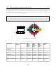
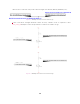

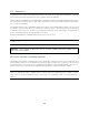

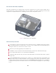
Table Of Contents

7.2 Interfaces
All Interface Boxes are provided with a DC power port and an 8-pin modular jack for Ethernet. Currently
Ouster offers two types of Interface boxes to support both 12V and 24V.
Interface Boxes (Standard) provided with Type 1 and Type 2 cables are assembled with integral cables
for connection to Ouster’s sensors. This cable cannot be disconnected from the interface box, as there
is no connector available.
The Interface Boxes (12V Compatible) with Type 3 cables are provided with an output connector and
a separate connectorized cable for connection to Ouster’s sensors. These Interface Boxes also have
a new GPS input connector capable of accepting operating TTL levels originating in a separate GPS
device containing static electricity dissipation circuitry.
Example: GPS Module compatible with Ouster Sensor
GPS Module.
Note: If you need support to configure the GPS to works with our sensor please contact sup-
port@ouster.io
.
Warning: RISK OF FIRE OR ELECTRIC SHOCK. DO NOT CONNECT THE GPS CONNECTOR DI-
RECTLY TO AN ANTENNA.
7.2.1 Interface Box 24V Compatibility (Standard)
The Interface Box that accompanies the OS2 is designed to allow the sensor to be operated for test
and evaluation purposes. It terminates the interface cable from the sensor, allows it to be powered
up and provides access to the sensor gigabit Ethernet Interface via a standard RJ45 connector. DC
Power to the sensor is provided to the Interface Box by the accompanying 24V DC Supply.
Note: The Ouster Interface Box is a support tool for use in laboratory environments to assist cus-
tomers in evaluating Ouster’s LiDAR sensor products and in the development of software. The In-
terface Box is not protected from ingress of moisture or solid particles and is not intended for use
outdoors.
18