
User Manual
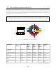
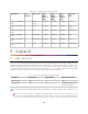
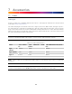


Table Of Contents

Electrical Characteristics
Ouster has characterized the cable resistance and contact resistance of our cables at room temper-
ature. This can be found below:
Table 7.2: Electrical Characteristics
Cable Maximum Cable Re-
sistance (ω/m)
Typical End to End Resis-
tance for 5m Cable (ω)
Admissible Nominal Oper-
ating voltage (V)
Type 1
(Thick)
0.110 0.45 24
Type 2
(Thin)
0.110 0.45 24
Type 3 0.042 0.3 12 / 24
For full sensor functionality, a minimum of 9.5 V must reach the sensor. To compensate for losses
through wire resistance, a higher voltage must be provided to the interface end of the cable, which
may be the Interface Box or the pigtail wires. If the sensor is below this voltage for at least 1 second,
the INPUT_VOLTAGE_LOW error will be triggered.
The following graph can be used as a guide to determine the appropriate input voltage to the sensor
connector for your desired cable length. The values on the graph were calculated using idealized cable
resistances derived from the AWG system and assumed maximum power draw from the sensor.
17