
User Manual
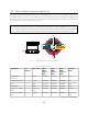
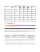
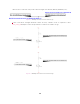


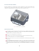
Table Of Contents

4.3 Direct Cable Connection and Pinout
The OS2 can be operated without the use of an Interface Box. In this case, a “pigtail” cable should
be used and wires should be connected by the user following the Pinout presented below. When used
with direct cable connection, the sensor should still be operated within the operating voltage specified
in section
Power Supply and Operating Voltage
Warning: Ouster is not responsible for any errors in wiring as a result of bypassing the Interface
Box and this activity may result in a voiding your warranty if it results in damage to the sensor.
The following guidelines for direct cable connection assume use of the Ouster-provided 24V 1.5A
power supply. Ouster cannot be held responsible for damage to the device if alternate is used.
Figure4.1: Cable pinout of on-sensor receptacle
Table4.1: Cable pinout wires
Net Name Pin
Number
Wire Color Wire
AWG
(Type-1,
24V)
Wire
AWG
(Type-2,
24V)
Wire
AWG
(Type-3,
12V)
Twisted
With
MULTIPUR-
POSE_IO
3 Purple 26 AWG 28 AWG 28 AWG N/A
SYNC_PULSE_IN 2 Yellow 26 AWG 28 AWG 28 AWG N/A
VCC 1 Red 22 AWG 22 AWG 18 AWG N/A
GROUND 7 Black 22 AWG 22 AWG 18 AWG N/A
TRP_1_P (Ether-
net)
5 White/Or-
ange
26 AWG 28 AWG 28 AWG Orange
TRP_1_N (Ether-
net)
4 Orange 26 AWG 28 AWG 28 AWG White/Or-
ange
continues on next page
12