
User Manual
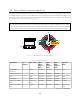
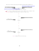


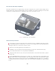
Table Of Contents

3.3 Operating Temperatures
Thermal requirements specific to Rev 06 are listed below. The sensor has three operating states in
order to manage high temperatures: Active, Shot Limiting, or Inactive. In the standard Active state
the sensor will perform to the range and precision specifications of the datasheet. When the sensor
reaches a certain temperature (see table below for reference), it enters Shot Limiting state and issues
an alert. In Shot Limiting state, the sensor reduces power to the lasers in order to reduce the thermal
load. While in this state, sensor range and precision may degrade by up to 20%. When the sensor
reaches the maximum operating temperature specified below, the sensor may become Inactive and
shut off.
Please contact
support@ouster.io with your sensor serial number to find out your sensor revision.
Table 3.1: Maximum thermal performance for Rev 06 OS2 Sensor
Convective Air Temp with Radial
Heatsink and Standard Base
Max temp before shot limiting 55ºC
Temp that shot limiting saturated (sensor may turn
off above this temperature)
61ºC
4 Electrical Interface
4.1 Power Supply and Operating Voltage
The OS2 Rev 06 Sensors are meant to operate at 12V and 24V nominal input voltage. A low voltage
warning will be triggered if the voltage at the sensor connector drops below 9.5V. The sensor will shut
down if this input voltage drops to 9V. The maximum input voltage is 34V for the OS2 sensor. When
used without the provided interface box, ensure that the power supply is compliant with the operating
voltage specified above and allows to supply at least 20 W.
4.2 Connection through the Interface Box
The Interface Box that accompanies the OS2 is designed to allow the sensor to be operated for test
and evaluation purposes in indoor environments only. It can be connected to the sensor with a cable
equipped with connectors on both ends. It allows the sensor to be powered up and provides access
to the sensor gigabit Ethernet Interface via a standard RJ45 connector. DC Power to the sensor is
provided to the Interface Box by the accompanying 24V DC power supply.
11