OS2 Hardware User Manual For Rev 06 OS2 Sensors Ouster Apr 05, 2022
Contents 1 Important Safety Information 1.1 Safety & Legal Notices . . . . . . . . . . . . . . . . . . . . . . . . . . . . . . . . . . . . . . . . 1.2 Proper Assembly, Maintenance and Safe Use . . . . . . . . . . . . . . . . . . . . . . . . . . 1.3 Sensor Cleaning . . . . . . . . . . . . . . . . . . . . . . . . . . . . . . . . . . . . . . . . . . . . 2 Sensor 2.1 Overview . . . . . . . . . . . . . . . . . . . . . . . . . . . . . . . . . . . . . . . . . . . . . . . . 2.2 OS2 Product Models . . . . . . . .
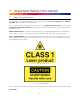
1 Important Safety Information 1.1 Safety & Legal Notices The OS2-128, OS2-64, and OS2-32 have been evaluated to be Class 1 laser products per 60825-1: 2014 (Ed. 3) and operate in the 865nm band. L’OS2-128, l’OS2-64, et l’OS2-32 répondent aux critères des produits laser de classe 1, selon la norme IEC 60825-1: 2014 (3ème édition) et émettent dans le domaine de l’infrarouge, à une longueur d’onde de 865nm environ.
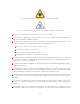
Figure1.3: This symbol indicates that the sensor emits laser radiation. Figure1.4: This symbol indicates the presence of a hot surface that may cause skin burn. The OS2 is a hermetically sealed unit, and is non user-serviceable. Use of controls, or adjustments, or performance of procedures other than those specified herein, may result in hazardous radiation exposure. Use of the OS2 is subject to the Terms of Sale that you agreed and signed with Ouster or your distributor/integrator.
ing of the laser and do not use optical instruments to view the laser. When operated in an ambient temperature >40°C, the metallic surfaces of the sensor may be hot enough to potentially cause skin burn. Avoid skin contact with the sensor’s base, lid and the heatsink when the sensor is operated under these conditions. The sensor should not be used in an ambient temperature above 50°C. The maximum safety certified ambient operating temperature is 50°C.
teur peut présenter des risques de brûlures pour la peau. Dans ces conditions, il est important d’éviter tout contact avec la partie supérieure, la base ou le dissipateur thermique du capteur. Le capteur ne doit pas être utilisé à une température ambiante supérieure à 50˚C. 50˚C est la température maximale certifiée d’opération sûre du capteur.
rates and resolutions other than the default values of 1024 x 10 Hz resolution. In all available combinations, the unit has been evaluated by an NRTL to remain within the classification of a Class 1 Laser Device as per IEC 60825-1:2014 (Ed. 3). Assemblage correct et utilisation sûre L’OS2 s’installe facilement en fixant la base sur un support percé de trous concordants, et en suivant les instructions d’interconnexion décrites dans la section Mounting Guidelines. Toute orientation de montage est acceptable.
Warm water Mild liquid dishwashing soap Spray bottle with clean water Spray bottle with mild soapy water 99% Isopropyl alcohol Warning: Avoid getting water into the power connector. Avoid using hard water when cleaning the sensor. Do not use acetone to clean the window. It will embrittle the polycarbonate. Do not wipe dirt directly from the sensor. Spray it off with warm water first. Procedure: Using the 99% isopropyl alcohol and a clean microfiber towel, wipe away bugs/mud/debris from the sensor.
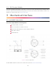
2.2 OS2 Product Models The OS2 is available with 128, 64, or 32 beams of vertical resolution and with Uniform, Gradient, Above Horizon, or Below Horizon beam spacing options. Product specs and more information on these configurations can be found on the OS2 product page. 3 Mechanical Interface 3.
Warning: The water ingress protection rating for the sensor is only valid if the I/O cable is plugged into the panel mount connector on the base of the sensor, and the locking collet rotated past the détente click to the properly locked condition i.e past the détente position. The cable and plug are an element of the sensor ingress protection system. Without the connected cable the ingress protection rating may be compromised.
3.3 Operating Temperatures Thermal requirements specific to Rev 06 are listed below. The sensor has three operating states in order to manage high temperatures: Active, Shot Limiting, or Inactive. In the standard Active state the sensor will perform to the range and precision specifications of the datasheet. When the sensor reaches a certain temperature (see table below for reference), it enters Shot Limiting state and issues an alert.
4.3 Direct Cable Connection and Pinout The OS2 can be operated without the use of an Interface Box. In this case, a “pigtail” cable should be used and wires should be connected by the user following the Pinout presented below.
Table 4.
GPIO of microcontrollers can produce drive strength of 5 mA min (Arduino, MSP430, etc.). Figure5.1: Example Circuits for 3.3 V and 5 V logic If the 5 mA drive strength minimum cannot be met, a buffer circuit is required to drive SYNC_PULSE_IN. Example circuits are provided for common 3.3 V and 5 V logic. Figure5.2: Example Circuits for 3.
5.2 MULTIPURPOSE_IO (M_IO) MULTIPURPOSE_IO (M_IO) is a configurable input or output channel accessible within the Interface Box Jumper J4 connected to the MULTIPURPOSE_IO pin of the Interface Box. Detailed information on how to configure this channel using the sensor TCP interface can be found in the API Guide. By default this channel is disabled. When this channel is configured as an OUTPUT, the M_IO sends a pulse sequence that can be used for time synchronization or event triggering outside the sensor.
7 Accessories 7.1 Cables Cable Types 3 types of cables are compatible with the OS2 sensors. Their physical characteristics are presented in the table Cable Characteristics. The cable and plug are an element of the sensor ingress protection. Without this, the ingress protection rating may be compromised. Bending the cable at a sharp angle directly after egress from the plug over mold should also be avoided.
Electrical Characteristics Ouster has characterized the cable resistance and contact resistance of our cables at room temperature. This can be found below: Cable Type 1 (Thick) Type 2 (Thin) Type 3 Table 7.2: Electrical Characteristics Maximum Cable Resistance (ω/m) Typical End to End Resistance for 5m Cable (ω) Admissible Nominal Operating voltage (V) 0.110 0.45 24 0.042 0.3 12 / 24 0.110 0.45 24 For full sensor functionality, a minimum of 9.5 V must reach the sensor.
7.2 Interfaces All Interface Boxes are provided with a DC power port and an 8-pin modular jack for Ethernet. Currently Ouster offers two types of Interface boxes to support both 12V and 24V. Interface Boxes (Standard) provided with Type 1 and Type 2 cables are assembled with integral cables for connection to Ouster’s sensors. This cable cannot be disconnected from the interface box, as there is no connector available.
Cable Connection and Pinout The OS2 can be operated without the use of an Interface Box.
7.2.2 Interface Box 12V (Compatible) This type of interface box is engineered for users who require the use of 12V DC power supply. These interface Boxes also have a new GPS input connector capable of accepting operating TTL levels that originate in a separate GPS device containing a static electric dissipation circuit. Figure7.1: Interface Box -12V compatibility Interface Box Specification 1 - This feature is optional for Rev 06 Sensor and above and is compatible with Type 3 Cables only.
Figure7.2: Components 7 - 3.3kω pullups to VCC_3P3|5 and green LED indicators for MULTIPURPOSE_IO and SYNC_PULSE_IN. Install a jumper on the respective header (J8 or J9) to enable the pullup. Figure7.3: J8 & J9 Circuitry 8 - 0.1” pitch, 4x2 pin header J7. GPS_TX (Pin 1) is only connected to connector J2; it is not connected to the sensor. 9 - 6-pin JST SH/SR connector J2. VCC_J2 (Pin 2) is connected to VCC_3P3|5 by installing a jumper on header J6.
Figure7.4: J7 Circuitry Figure7.
Connectors Connectivity Guide: RJ45: Ethernet connection to a computer 6-PIN JST SH/SR: GPS connector port Barrel Jack: 24V DC power supply Figure7.6: Connector Outline Electrical Characteristics The Type 1 and Type 2 cable Interface Boxes are rated 24 Vdc, 1.1 A and supports all Ouster sensors. The Type 3 cable Interface Box is rated 12 Vdc, 3.3 A and 24 Vdc, 1.1 A. This Interface Box supports 24V operation on all Ouster sensors, and 12V operation for Rev 05 and above sensors only.
Overcurrent Protection Type 1 and Type 2 cable Interface Boxes Interface Boxes are provided with thermistor type overcurrent protection to supplement the internal overcurrent protection in the sensor. The thermistor is soldered in place and is not user replaceable. The Type 3 Interface Box contains a user replaceable 5A mini blade fuse. When replacing this fuse, use only a Littelfuse - Type 891005 fuse. Use of any other fuse may lead to a risk of fire.
Selecting a Power Supply Cord/Cordset If purchasing a power supply locally, it should be supplied with an appropriate power supply cord or cordset for use with the power supply. If it’s necessary to select a power supply cordset for the Ouster supplied power supply, it should be safety certified by a test house acceptable to the local region of use, supplied with an IEC 60320, Type C6 cord connector to mate with the power supply and a plug for connection to an AC outlet with an earthing contact/pin.
8 GPS/GNSS Synchronization Guide This guide will explain how to physically connect a GPS to your Ouster sensor and synchronize the Ouster sensor timestamp to an NMEA sentence. 8.1 Setting up your GPS/GNSS It is important to ensure you have configured your GPS according to the manufacturer’s specifications.
Connection using the GPS Port Connect the PPS output from your GPS to the sync_pulse_in pin of the GPS connector to be plugged on the Ouster Interface Box, pictured below in yellow. Connect the NMEA UART output from your GPS to the multipurpose_io pin of the GPS connector to be plugged on the Ouster Interface Box, pictured below in magenta. Connect the ground output from your GPS to the GND pin of the GPS connector to be plugged on the Ouster Interface Box, pictured below in gray. Figure8.
Figure8.2: J7 Circuitry Figure8.
Parameter LOGIC LOW LOGIC HIGH Table8.2: MULTIPURPOSE_IO - INPUT Interface Requirements Min Voltage Max Voltage Min Driver Current 2.9 V 30 V 3mA @3.3V~5V, 5mA at 24V and higher -30 V 2V N/A 8.3 Configuring the Ouster Sensor Please refer to the GPS configuration section in the software user manual to configure your sensor to synchronize its timestamp with the GPS.