
Instruction Manual

8
Caution
Once the heating cable has been run for the entire section, begin fastening it with application tape or
good quality Listed fiberglass tape (listed fiberglass tape with temperature rating higher than 80°C
(175°F) to the pipe.
In order to keep the thermostat and the entire length of heating cable tightly in contact with the pipe,
circumferential bands of tape should be installed at approximately 15cm (6in) intervals.
The thermostat should be placed on the coldest end of the pipe.
If necessary, hand-tightened plastic wire ties, which have a temperature rating higher than 80°C
(175°F), may also be used to secure the cable.
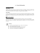
For plastic pipe systems, wrapping the plastic pipe with aluminum foil before installing the heating
cable will improve heat transfer and provide more even heat distribution.
Warning:
Substandard
adhesive tapes may allow the cable to move at normal cable
operating temperatures and could result in overheating, fire, or electrical shock.
Warning:
Do not use metal attachments such as pipe straps or tie wire to attach the heater
cable, as these may damage heating cable and cause electrical arcing or fire.
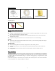
Bending, Crossing and Cutting the Heating Cable
The minimum bending radius is 8mm (5/16in). Do not bend the heating cable along the flat plane.
Sharper bends than 8mm (5/16in) can damage the heating element.
Warning:
This heating cable is not a parallel resistance cable. It cannot be cut to the desired
length. Once cut, the cable cannot be repaired. Also, the cable should never be overlapped.
Thermal Insulation
After installing the heat tracing system, visually inspect the cable to ensure it is properly installed and
there are no signs of damage.
Use a maximum 17mm (0.5in) fiberglass (including pre-formed fiberglass) insulation over the cable
and the thermostat to keep the heat tracing system working more efficiency.
In order to protect the insulation from moisture, and physical damage, and to ensure the proper
performance of the heat tracing system, a protective barrier (with an additional waterproof barrier
over-wrapped in the opposite direction) should be installed over the system.
Apply “Electric Traced” labels to the insulation weather barrier at intervals of 3 m (10 ft) along pipe,
as a warning to maintenance personnel.