INSTALLATION MANUAL INS-RF-R-202206-00 120V Preassembled Heating Cable for Roof and Gutter De-Icing RF-R Series ORF-R Series BGDC1-1A Series RFG-R Series MRF-R Series DRF-R Series
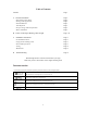
Table of Contents Caution Page 3 A.General Information How Heating Cable Work Heating Cable Application Included Material Tools Required Receipt, Storage and Transportation Before installation Page 4 Page 4 Page 4 Page 5 Page 5 Page 5 Page 5 B.Select of The Proper Heating Cable Length Page 6-10 C. Installation Instructions Page 11 Page 11 Page 11 Page 11 Page 12 Page 13 Pre-Installation Check Laying Out the Heating Cable Electrical Requirements Testing Maintenance D.
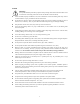
Caution Warnings: (This symbol identifies particularly important safety warnings that must be followed. Failure to do so could cause overheating and result in serious fire hazard or electrical shock). Failure to handle, improper installation, use, and/or maintenance of electrical heating cable may result in ice dam formation or injury or death from electric shock or fire.
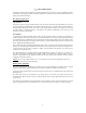
A.General Information This guide provides a basis for designing a roof and gutter deicing system. It also covers the installation of Roof and Gutter De-icing Heating Cables in residential applications. This instruction manual includes information on testing and periodic maintenance. How Heating Cable Work The Problem Snow and ice melt as a result of either exposure to the sun or from heat rising from the building. As the water runs into cold gutters and drainpipes, it can refreeze, forming layers of ice.
Warnings: Do not use to remove ice dams that have already formed or clear the roof of ice and snow. Do not use on roofs with wooden shingles, rubber roofs or composite (tar and gravel) roofs. Do not use on wooden gutters or downspouts. Do not use for any other purposes, such as melting snow or ice on sidewalks or pipes freezing protection.
B.Select the Proper Heating Cable Length First, several important terms should be defined as below: Specification Table An accurate estimate of the cable length you need is critical because you cannot change the cable length by cutting, splicing, or altering it in any way. Item Starting Point Heating Length (ft.) 20 30 60 80 100 120 140 160 180 200 240 Power Output (Watts) 100 150 300 400 500 600 700 800 900 1000 1200 Amp. (@120V) 0.83 1.25 2.50 3.33 4.17 5.00 5.83 6.67 7.50 8.33 10.
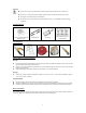
Roofline To maintain a continuous path on the roof for water run-off, route the heating cable in a “zigzag” fashion as shown. A drip loop extends at least 6 cm (2.5in) from the roof edge to direct water into the gutter or to the ground. The cable must extend above the overhang into the section of the roof above the heated section of the house. Also, to make a continuous path for the water, extend the heating cable all the way down to the gutter.
Valleys Attach the heating cable up and down the valley and keep two parallel lines at least 5cm (2in). away. Lay heating cable up to two-thirds of the length of each valley, a minimum of 91cm (3ft.), and return to form a double run of heating cable in the gutter. Extend the cable higher if the heated area of your house below your roof is farther up the valley.
of cable bottom of the gutter to prevent heat loss. 3. Sometimes in a wide gutter, width > 15cm (6in), snow and ice can bridge over a single heating cable creating a runnel that prevents water from getting into the gutter and downspouts. To maintain a continuous path for water run-off, use two parallel heating cables in the gutter. When using two parallel runs of heating cable, separate the two runs of heating cable with a spacer every 15cm (6in).
Skylight (Special roof areas) When installing the heating cable around special roof area such us skylight, use a “zigzag pattern”. Maintain the triangle base at 38cm (15in). However, the height of the triangles needs to be greater than those along the roofline. Increase the triangle height till it extends to about 15cm/6in into the roof section above the heated portion of the house. Caution: Triangle heights must not exceed 6m (20ft).
C. Installation instructions Pre-Installation Check The heating cable should be tested to ensure electrical integrity with at least a 500 Vdc megohmmeter (megger) between the grounding pin and any of the other two pins. Minimum resistance should be 20 megohms. Readings below 20 megohms indicate the electrical insulation has been damaged and the heating cable must be replaced. Ensure that the service voltage available is correct for the heating cable.
Electrical Requirements This cable must be plugged into a 120 Volt A/C outdoor receptacle that is grounded. The indicator light on the power plug will be illuminated when your cable is energized. This allows you to know the cable is energized in cold weather and, on the other hand, reminds you to turn off the cable in warm weather, which will avoid overheating and reduce energy usage. Make sure that the heating cable load you are connecting is within the rating of your electric control system.
Maintenance While the cable is operating, check to ensure a complete path is available for water to get to the ground. There should be no ice buildup above the cables, and icicles should not form at the roof edge. Inspect the cable, including the plug at the beginning of every heating season and monthly during operation. Clear all gutters and downspouts of combustible debris such as leaves, pine needles, seeds or windblown trash.
D. Troubleshooting Symptom Circuit Breaker Trips Problem causes Correction Circuit breaker is undersized Replace the circuit breaker if defective or improperly sized. Defective circuit breaker Check to see if existing power wire sizing is compatible with larger-sized breakers. Parts of the electrical circuit become wet Use a weatherproof receptacle. Physical damage to the heating cable may be causing a direct short Check for where there may have been maintenance work done.