Type ETO2 © 2013 OJ Electronics A/S 67221 12/13 (JRK) Controller for ice and snow melting English Français GREEN COMFORT Maximum comfort with low energy consumption
English Instruction ETO2 is an electronic controller for fully automatic, economical ice and snow melting on outdoor surfaces and in gutters. Ice forms due to a combination of low temperature and moisture. ETO2 detects both temperature and moisture, and the ice and snow melting system will usually only be activated if ice or snow is present. ETO2 is suitable for controlling both electric heating cables and hydronic heating pipes. Product programme ETO2-4550 Thermostat.
English / Instruction Type ETO2 INSTRUCTION Supply voltage to actuator (mixing valve) ..................................max. 48 V AC/DC / max. 2 A On/off differential.........................................................1.8°F / 1°C Temperature range..................................... -4/+50°F / -20/+10°C Ambient temperature..................................... 32/122°F / 0/+50°C Ambient air humidity........................................................10-95% Enclosure rating.......................
English / Instruction Type ETO2 (25 m) cable, which can be extended up to approx. 656 ft - (200 m) using standard installation cable: 6x16 AWG (6x1.5 mm² ) for ETOG and 4x16 AWG (4x1.5 mm² ) for ETOR. The ETF cable can be extended up to approx. 164 ft (50 m) in length. Sensor cables must be installed in accordance with current regulations. They must never be installed parallel to power cables as electrical interference may distort the sensor signal.
English / Instruction Type ETO2 Remote control (fig. 15): The forced heat and standby functions can be remotely controlled by wiring ETO2 to external buttons/relays (normally open). Connect external standby button to terminals 33-34. Connect external forced heat button to terminals 35-36. INSTRUCTION Testing snow melting system After completing installation and application setup, it is recommended that the snow melting system is tested. 1. Adjust SET TEMP in the setup menu to max. temperature. 2.
English User Manual CONTENTS Glossary. . . . . . . . . . . . . . . . . . . . . . . . . . . . . . . . . . . . . . . . . . . . . . . . . . . . . . . . . . . . . . . Page Introduction.. . . . . . . . . . . . . . . . . . . . . . . . . . . . . . . . . . . . . . . . . . . . . . . . . . . . . . . . . . . . . Page Startup. . . . . . . . . . . . . . . . . . . . . . . . . . . . . . . . . . . . . . . . . . . . . . . . . . . . . . . . . . . . . . . . Page Operation. . . . . . . . . . . . . . . . . . . . . . . . . . .
Type ETO2 English / User Manual In hydronic mode, the supply sensor maintains the required supply water temperature while the system is active. When heat is demanded, both the circulation and main pumps are activated and the valve is opened 20% for 1 minute to let the system stabilise. When there is no need for ice or snow melting, the system activates the circulation pump for 1 minute every 15 minutes to check whether the return water temperature has dropped below the required “idle temp.
Type ETO2 English / User Manual OPERATION ETO2 is equipped with an easily operated encoder button (turn and press) and a display which describes the current situation. The display is backlit and is illuminated by pressing the encoder button (OK). The illumination is automatically switched off after 30 seconds. Press the encoder button and the main menu will be shown on the display. Turn the button to scroll through the options.
English / User Manual RETURN W. Type ETO2 Return water temperature, hydronic application only. ##.#°C Fault message, fault type will be displayed. Red LED on front of unit will flash. ALARM NO APPLICATION INFO SHOW INFO APP: E. 1-ZONE INSTRUCTION SW VERSION 1.
Type ETO2 English / User Manual OFF TEMP 2 OFF The lowest operating temperature for zone 2 can be set here. The setting can be as low as -3.9°F (-20°C), or OFF can be selected. OFF = no limit. To change the minimum cut-off temperature, press OK, turn the encoder button to the desired value and confirm with OK. AFTERRUN 1 2:00 Afterrun time, zone 1: An afterrun duration of between 0 and 18 hours can be set here.
English / User Manual All ETO2 factory settings can be restored here. Selecting this option deletes all customised settings. FACTORY RESET In the event of setup failure in the STARTUP menu, or whenever new hardware is connected, the primary setup must be changed in the STARTUP menu. Select PASSWORD and turn the encoder button to the factory code (1202). The controller will then return to the STARTUP menu, see STARTUP.
English / User Manual Type ETO2 TROUBLESHOOTING If faults occur in the ice and snow melting system, it is advisable to check the ETO2 setup. Activate the menu by pressing the encoder button and select SHOW INFO to display the application settings. If there are errors in the setup, activate REINSTALL using factory code 1202. Check that all connections are made correctly, and that cables are fastened in the clamps. For answers to FAQ, please visit our website: www.ojelectronics.
Type ETO2 MENU OVERVIEW: STARTUP SELECT SCALE CELSIUS FAHRENHEIT SENSOR 1 ETOG ETOR SENSOR 2 OFF ETOG ETOR OUTDOOR SENSOR OFF ETF APPLICATION ELECTRIC 1-ZONE ELECTRIC 2-ZONE ELECTRIC 2-STEP WATER BASED MAIN MENU ZONE 1 ZONE 2 SENSOR 1 SENSOR 2 MOIST 1 MOIST 2 OUT. TEMP SUPPLY W. RETURN W. ALARM SHOW INFO SETUP RESTART EXIT ALARM MENU ACTIVE ALARMS RETURN TEMP LOW SUPPLY TEMP HIGH RETURN SENSOR SUPPLY SENSOR TEMP SENSOR 1 TEMP SENSOR 2 OUTDOOR SENSOR SENSOR HEATER FROST PORTECT EXIT OPERATION OFF OFF ##.
Type ETO2 1-zone electric heating with ETOG sensor Installation of ETOR gutter sensor and ETF outdoor sensor Fig. 4 1-zone electric heating with ETOR/ETF sensor BR978A23a BR978A12a Fig. 3 Fig. 2 30 © 2013 OJ Electronics A/S BR978A24a Installation of ETOG ground sensor BR978A31a Fig.
Type ETO2 Fig. 7 ETOR connection Fig. 6 ETOG connection Fig. 8 Heating cable connection, example BR978A05c 2-zone electric heating (roof/ground) BR978A25a Fig.
Type ETO2 Fig. 10 Advanced 2-stage connection (Y/Δ) Fig. 11 1-zone hydronic heating control for controling the supply water temp. with mixing valve BR978A04a BR978A04a Advanced 2-stage electric heating control (Y/Δ) BR978A28a Fig.
Type ETO2 1- or 2-zone hydronic heating control, simple (same application setup as 1- or 2-zone electric heating control) Fig. 13 Hydronic mixing valve connection BR978C02a Fig. 12 33 © 2013 OJ Electronics A/S Hydronic pump connection BR978A29a BR978A20a Fig.
Type ETO2 Fig.
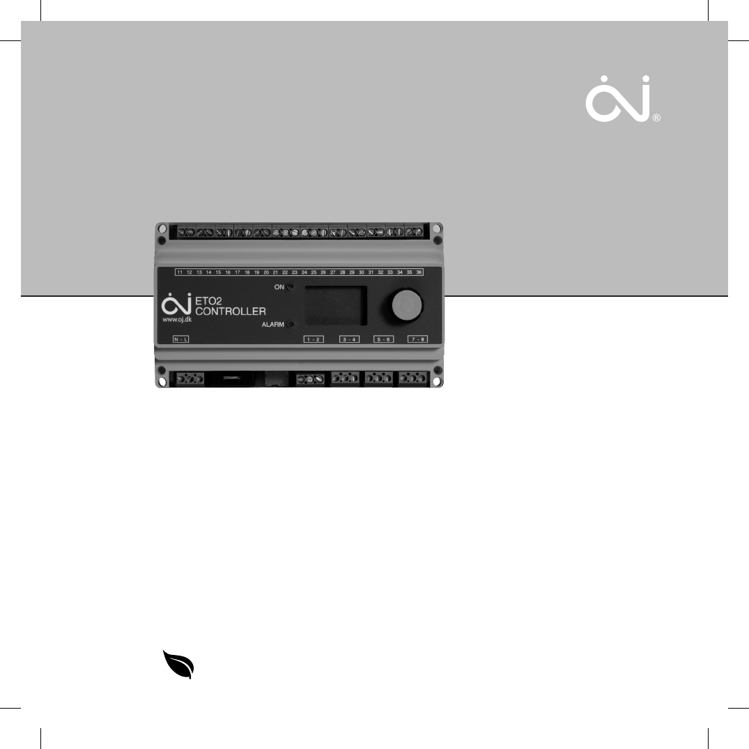
Type ETO2 ETO2 controller, terminal overview BR978A03h Fig.
® The trademark is registered and belongs to OJ Electronics A/S · © 2013 OJ Electronics A/S OJ ELECTRONICS A/S Stenager 13B · DK-6400 Sønderborg Tel.: +45 73 12 13 14 · Fax +45 73 12 13 13 oj@ojelectronics.com · www.ojelectronics.