ABS / AIR BAG 2004 USER GUIDE
IMPORTANT NOTICES SAFETY All Danger, Warning and Important notes must be followed for your safety. These safety messages are in the following formats: DANGER: Means you risk possible loss of life. WARNING: Means you risk possible bodily harm. IMPORTANT: Means that the information demands special attention or that you risk damage to the vehicle or the tool. Note: are added to provide clarity and helpful tips. These safety messages cover situations SPX is aware of.
ABS / AIR BAG 2004 SOFTWARE for the NEXT GENERATION INFORMATION SYSTEM TOOL USER GUIDE
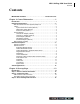
ABS / Air Bag 2004 User Guide Contents Contents IMPORTANT NOTICES. . . . . . . . . . . . . . . . . . . . . . . . . . . inside front cover Chapter 1: General Information . . . . . . . . . . . . . . . . . . . . . . . . . . 1 Introduction . . . . . . . . . . . . . . . . . . . . . . . . . . . . . . . . . . . . . . . . . . . . . . . . . 1 Equipment Descriptions . . . . . . . . . . . . . . . . . . . . . . . . . . . . . . . . . . . . . . . 2 Next Generation Information System (NGIS) Tool . . . . . . . . . . . .
ii ABS / Air Bag 2004 User Guide Contents Chapter 3: Datastream . . . . . . . . . . . . . . . . . . . . . . . . . . . . . . . . . 19 About Datastream . . . . . . . . . . . . . . . . . . . . . . . . . . . . . . . . . . . . . . . . . . . . 19 Automatic Diagnostic Code Triggered Record . . . . . . . . . . . . . . . . . . . . 19 Basic Datastream Procedure . . . . . . . . . . . . . . . . . . . . . . . . . . . . . . . . . . . 19 Datastream Functions . . . . . . . . . . . . . . . . . . . . . . . . . . . . . . .
ABS / Air Bag 2004 User Guide Contents Chapter 8: Vehicle Info . . . . . . . . . . . . . . . . . . . . . . . . . . . . . . . . . 55 Specifications. . . . . . . . . . . . . . . . . . . . . . . . . . . . . . . . . . . . . . . . . . . . . . . Related TSBs . . . . . . . . . . . . . . . . . . . . . . . . . . . . . . . . . . . . . . . . . . . . . . . System Type . . . . . . . . . . . . . . . . . . . . . . . . . . . . . . . . . . . . . . . . . . . . . . . . PROM Identification . . . . . . . . . . . . . . . . . .
This page is intentionally blank
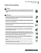
ABS / Air Bag 2004 User Guide Safety Precautions Safety Precautions Danger: • When an engine is operating, keep the service area WELL VENTILATED or attach a building exhaust removal system to the engine exhaust system. Engines produce carbon monoxide, an odorless, poisonous gas that causes slower reaction time and can lead to serious injury or death. Warning: • When working with hydraulic or fuel lines, liquids under pressure may escape and create a dangerous condition.
ABS / Air Bag 2004 User Guide Safety Precautions Important: • To avoid damaging the NGIS tool or generating false data, make sure the vehicle battery is fully charged and the connection to the vehicle DLC is clean and secure. • Never disconnect or reconnect any electrical connector while the ignition is on. Damage to the ABS control unit may result. • Do not hammer speed rings into the hub or tap on speed sensor components (sensor, sensor rings, etc.).
ABS / Air Bag 2004 User Guide Chapter 1: General Information Introduction 1: General Information Introduction ABS / Air Bag 2004 is a software program for the Next Generation Information System (NGIS) tool. With the software installed (and unlocked) in the NGIS tool, and with the tool properly connected to a vehicle’s electronic control unit (ECU), you can use the software to read the vehicle’s anti-lock brake system (ABS) and air bag information and to perform device control tests.
2 ABS / Air Bag 2004 User Guide Equipment Descriptions Equipment Descriptions Next Generation Information System (NGIS) Tool The NGIS tool (purchased separately) is a portable, hand-held tool. The Pathfinder 2001 (or newer) software and the ABS / Air Bag 2004 software must be installed in the NGIS tool before you can use the NGIS tool for testing the air bag and brake systems. This User Guide assumes you are familiar with using the NGIS tool. If necessary, refer to the User Guide for the NGIS tool.
ABS / Air Bag 2004 User Guide Chapter 1: General Information Equipment Descriptions Cables DB25 Power Cable (3305-72) The cable used to connect the NGIS tool to the data link connector (DLC) of a vehicle’s electronic control unit (ECU) depends on the type of vehicle being tested. The two most common cables are shown below. They are the System Smart 25-pin cable (3305-73) and the DB25 power cable (3305-72). An optional extension cable may also be used.
4 ABS / Air Bag 2004 User Guide Equipment Descriptions Vehicle Adapters Universal “C” Adapter (3305-74) The vehicle adapters are used with the DB 25 power cable, shown on the previous page. The adapter used depends on the vehicle being tested. Some of the most common adapters are shown below. Note: The Air Bag / ABS software tells you which adapter must be used for the vehicle you are testing. For details, refer to “Step 1: Enter the Vehicle Information” on page 13.
ABS / Air Bag 2004 User Guide Chapter 1: General Information Equipment Descriptions Battery Adapter (212638) GM Adapter (212633) 1 2 2 1 Figure 1.9: GM Adapter The GM adapter is for GM vehicles. The adapter has the following components: Item 1 DLC Connector - connects to the data link connector (DLC) of the vehicle’s electronic control unit. Item 2 8-Pin Connector - connects to the 8-pin connector on the DB 25 power cable. Sumitomo Adapter (3305-19) Figure 1.
6 ABS / Air Bag 2004 User Guide Software Description Software Description Software Installation Before using the ABS / Air Bag 2004 software, the software must be installed in the NGIS tool and “unlocked” with a Smart Card. The software is either preinstalled in the NGIS tool, provided on a compact disc or flash, or can be downloaded from the SPX web site. From the Application Manager screen, you select Scan Diagnostics and then press the ENTER key.
ABS / Air Bag 2004 User Guide Chapter 1: General Information Software Description Vehicle Identification Screen When you select ABS / Air Bag 2004 from the Scan Diagnostics menu, the first Vehicle Identification screen appears. Vehicle Identification - Required Cables Screen Figure 1.15: Vehicle Identification - Required Cables Screen Figure 1.
8 ABS / Air Bag 2004 User Guide Software Description Diagnostic Menu Screen Datastream When you select Datastream from the Diagnostic menu, the following screen appears. Figure 1.16: Diagnostic Menu Screen The Diagnostic Menu screen contains a menu of the test options available for the vehicle being tested. The next few pages show and briefly describe each of the options on the Diagnostic menu. Note: The screen shown above is only an example.
ABS / Air Bag 2004 User Guide Chapter 1: General Information Software Description Custom Datastream When you select Custom Datasteam from the Diagnostic menu, the following screen appears. Diagnostic Codes (or Read Codes and Clear Codes) The diagnostic trouble code option(s) that appear on the Diagnostic Menu screen vary depending on the vehicle being tested.
10 ABS / Air Bag 2004 User Guide Software Description Post Collision Test Pathfinder When you select Post Collision Test from the Diagnostic menu, several step-by-step instruction screens, similar to the following screen, appear. When you select Pathfinder from the Diagnostic menu, the following screen appears. Figure 1.22: Pathfinder Screen Figure 1.21: Post Collision Test Screen The screens provide instructions for testing air bags after repair(s).
ABS / Air Bag 2004 User Guide Chapter 1: General Information Software Description Vehicle Info Controller ID When you select Vehicle Info from the Diagnostic menu, the following screen appears. When you select Controller ID from the Diagnostic menu, the following screen appears. Figure 1.23: Vehicle Info Screen Figure 1.
12 ABS / Air Bag 2004 User Guide Vehicle Applications Special Tests Vehicle Applications When you select Special Tests from the Diagnostic menu, the following screen appears. The ABS / Air Bag Vehicle Applications Reference Guide is available as a portable document format (pdf) file that installs on the PC during the NGIS Software installation (see “Software Installation” on page 6). The Reference Guide contains a listing of the vehicles and ECUs that the ABS /Air Bag 2004 software works with.
ABS / Air Bag 2004 User Guide Chapter 2: Start-up Steps Introduction 2: Start-up Steps Introduction All vehicle setups require a specific cable connection to the vehicle Data Link Connector (DLC). To determine the specific cable required for a vehicle, you must first enter the vehicle information. After you have done this, the screen displays the specific cable information for the vehicle. You then use this information to connect the correct cable to the DLC and proceed with the vehicle diagnostics.
14 ABS / Air Bag 2004 User Guide Step 1: Enter the Vehicle Information 5 To enter new information for a vehicle, do the following: a Select the vehicle manufacturer and press the ENTER key. This displays the selected vehicle description in the top part of the screen and changes the middle part of the screen to the next screen of a series of screens, as shown below. Note: The screens shown below are only examples. The screens that actually appear are different for each vehicle. Figure 2.
ABS / Air Bag 2004 User Guide Chapter 2: Start-up Steps Step 1: Enter the Vehicle Information 6 To reuse saved information for a vehicle already tested, do the following: a Press the Reuse function key. This displays the Reuse Vehicles screen, which contains a list of saved vehicle descriptions. 7 After you have entered new vehicle information or selected a vehicle description to reuse, the Required Cables illustration displays on the Vehicle Identification screen.
16 ABS / Air Bag 2004 User Guide Step 2: Connect the Cable Step 2: Connect the Cable The method used to connect the NGIS tool to a vehicle’s electronic control unit (ECU) depends on the vehicle’s configuration as follows: • A vehicle equipped with an On Board Diagnostics Two (OBD II) vehicle management system supplies both communication and 12-volt power through a standardized J-1962 data link connection (DLC).
ABS / Air Bag 2004 User Guide Chapter 2: Start-up Steps Step 2: Connect the Cable Non-OBD II Vehicle Cable Connection 2 This type of connection generally requires the DB25 Power cable (3305-72) or another vehicle-specific cable. Connect the cable’s 25-pin connector to the DB25 port on the top of the NGIS tool. Finger tighten the connecting screws (see Figure 2.11). Note: Extension cable (3305-71) can be used between the NGIS tool and the DB25 Power cable. Refer to “Extension Cable (3305-71)” on page 3.
18 ABS / Air Bag 2004 User Guide Step 3: Select the Diagnostic Function Step 3: Select the Diagnostic Function After connecting the cable, the NGIS tool should still display the Vehicle Identification - Required Cables screen. 3 Select the option for the diagnostic function you want to perform and press the ENTER key. 4 For specific steps for each function, refer to the following chapters: • Datastream - “Chapter 3: Datastream” on page 19.
ABS / Air Bag 2004 User Guide Chapter 3: Datastream About Datastream 3: Datastream The Datastream function lets you view live ABS and air bag data from a vehicle’s electronic control unit (ECU). This chapter describes how to use the Data-stream function. Basic Datastream Procedure Use the following steps to obtain a basic understanding of how the Datastream function works. Note: Before performing this procedure, follow the instructions in “Chapter 2: Start-up Steps” on page 13.
20 ABS / Air Bag 2004 User Guide Datastream Functions Datastream Functions There are several functions you can use on the Datastream screen. Most of the functions are activated with the function keys at the bottom of the screen. These functions, described in detail on the next few pages, include the following: • Record and Playback – records the data for viewing again at a later time. (See page 21.
ABS / Air Bag 2004 User Guide Chapter 3: Datastream Datastream Functions Record and Playback The Record function lets you record up to 150 one-second frames of data (75 frames that occur before pressing the Record function key and 75 frames that occur after pressing the key). The Playback function lets you replay recorded data. You can also save and delete recordings.
22 ABS / Air Bag 2004 User Guide Datastream Functions Graph / Analog / LED / Digital About Digital Display The Graph/ Analog / LED / Digital function lets you change the display type for each line on the Datastream screen. Depending on the type of data on a line, you can change a selected line from digital to a graphical or LED display. You can also set some of the lines to display analog meters (gauges) at the top of the screen.
ABS / Air Bag 2004 User Guide Chapter 3: Datastream Datastream Functions About Graph Display About Analog Display If a selected line’s data reading is a number (such as 14.4 V, 1.1 V, or 23 Amps), you can use the Graph function key to display the line’s data as a graph. For example, see Figure 3.7 and Figure 3.8. Notice how the function key changes to Analog so you can change the display to Analog (see the next section). When a selected line’s data reading is displayed as a graph (seeFigure 3.
24 ABS / Air Bag 2004 User Guide Datastream Functions Lock To Top The Lock function lets you “lock” selected data lines so they are always included when recording and printing, even if they are below the viewable area of the screen. The To Top function lets you move a selected data line to the top of the Datastream screen. Note: Generally, printing and recording include only the data items within the viewable area of the data display.
ABS / Air Bag 2004 User Guide Chapter 3: Datastream Datastream Functions Freeze Frame Pathfinder The Freeze Frame function lets you “freeze” the data display on the Datastream screen and lets you view past data frame-by-frame. The Pathfinder function on the Datastream screen’s More menu provides quick access to the Pathfinder software’s menu options.
26 ABS / Air Bag 2004 User Guide Datastream Functions Print Zoom The Print function on the Datastream screen’s More menu lets you print the data currently displayed on the screen. The Zoom function on the Datastream screen’s More menu lets you magnify the view of each data line on the Datastream screen. To print the data, follow these steps: Note: This function applies to digital, graph, and LED display lines. The function can be used for the normal display or for a “frozen” display.
ABS / Air Bag 2004 User Guide Chapter 3: Datastream Datastream Functions Sort The Sort function on the Datastream screen’s More menu lets you rearrange the data on the Datastream screen alphabetically or with either locked or graphed lines at the top of the screen. Note: You can also use the To Top function to rearrange the data lines. For details, refer to “To Top” on page 24. To sort the data lines, follow these steps: Figure 3.
28 ABS / Air Bag 2004 User Guide Datastream Functions English / Metric Units The English / Metric Units function on the Datastream screen’s More menu lets you change the units of measure for the data from English to Metric, or vice versa. To change the units of measure, follow these steps: Figure 3.19: Sort Options Screen 4 5 From the Sort Options screen (Figure 3.
ABS / Air Bag 2004 User Guide Chapter 3: Datastream Datastream Functions Show / Hide LED Bar The Show / Hide LED Bar function on the Datastream screen’s More menu lets you displays (or remove) a row of LED readings directly above the status line and function keys. The LED readings are for a predefined set of frequently monitored switches. To show or hide the LED bar, follow these steps: Figure 3.23: Datastream Screen - LED Bar Displayed 4 Figure 3.
30 ABS / Air Bag 2004 User Guide Datastream Functions Show / Hide Analog When analog gauges are displayed at the top of the Datastream screen, the Show / Hide Analog function on the More menu lets you temporarily hide the gauges or display them again. Note: To originally display analog gauges, or to entirely turn them off, refer to “Graph / Analog / LED / Digital” on page 22. To hide or show the analog gauges, follow these steps: Figure 3.
ABS / Air Bag 2004 User Guide Chapter 4: Custom Datastream 4: Custom Datastream The Custom Datastream function lets you select specific data items to display on the standard Datastream screen. 2 a Use the Up and Down Direction key to select an item to include in the display. b Press the ENTER key. A check mark appears in the box on the left side of the item.
32 This page is intentionally blank
ABS / Air Bag 2004 User Guide Chapter 5: Diagnostic Codes (Read / Clear Codes) 5: Diagnostic Codes (Read / Clear Codes) The Diagnostics Codes (or Read Codes and Clear Codes) functions let you read, review, and clear diagnostic trouble codes (DTCs) for a vehicle. The diagnostic trouble code option(s) that appear on the Diagnostic Menu screen vary depending on the vehicle being tested. For some vehicles, the menu option is Diagnostic Codes (see Figure 5.
34 ABS / Air Bag 2004 User Guide Read Codes Read Codes The Diagnostic Codes, Read Codes option lets you use the NGIS tool to read DTCs from a vehicle that allows access to the vehicle’s electronic control unit (ECU) through a data link connection (DLC). Depending on the vehicle being tested, the Read Codes procedure varies. This section includes two separate Read Codes procedures, as follows: • Read and Display Codes (below) - this procedure reads and displays the DTCs in one procedure.
ABS / Air Bag 2004 User Guide Chapter 5: Diagnostic Codes (Read / Clear Codes) Read Codes 3 Select either History Codes or Current Code as follows: Note: For some vehicles, the menu options may be Past and Present instead of History and Current. • • Select History Codes and press the ENTER key to display history (or past) codes for the vehicle. History Codes are diagnostic trouble codes that have occurred intermittently.
36 ABS / Air Bag 2004 User Guide Read Codes Figure 5.8: Diagnostic Trouble Codes Menu Screen Figure 5.10: Read Codes Test Screen 2 4 Select Read Codes and press the ENTER key. This displays an instruction or information screen, similar to the following screen. The test screen displays the codes being read and the time remaining for the test. When the test is finished, the word “Wait” changes to “Test completed.” When this happens, press the EXIT function key to continue.
ABS / Air Bag 2004 User Guide Chapter 5: Diagnostic Codes (Read / Clear Codes) Review Codes Review Codes 3 For some vehicles, the Review Codes option appears on the Diagnostic Trouble Codes menu screen. This option lets you review trouble codes after initially reading them. If another menu appears, select KOEO on Demand and press the ENTER key. This displays the list of codes on the Review Codes screen. Note: If there are no codes to display, a message screen states that the code library is empty.
38 ABS / Air Bag 2004 User Guide Clear Codes Clear Codes For some vehicles, the Clear Codes option appears on the Diagnostic Trouble Codes menu screen. This option lets you clear DTC codes from a vehicle. For some vehicles, this procedure also clears codes stored in the ABS / Air Bag software. After reading and / or reviewing the diagnostic trouble codes, use the following steps to clear the codes from the vehicle.
ABS / Air Bag 2004 User Guide Chapter 5: Diagnostic Codes (Read / Clear Codes) Self Diagnostics Self Diagnostics For some vehicles (Ford), the Self Diagnostics option appears on the Diagnostic Trouble Codes menu screen. This function is a diagnostic test that is activated and managed by the vehicle. At the completion of the test, a list of diagnostic trouble codes displays on the screen.
40 ABS / Air Bag 2004 User Guide Self Diagnostics 2 Select Self Diagnostics and press the ENTER key. This displays the Self Diagnostics menu screen. Figure 5.23: Self Diagnostic Test Instruction Screen Figure 5.21: Self Diagnostics Menu Screen 3 Select On Demand Test and press the ENTER key. This displays the On Demand Test screen. 5 Read and follow the instructions on the screen and press the OK function key. 6 One or more instruction screens may appear.
ABS / Air Bag 2004 User Guide Chapter 5: Diagnostic Codes (Read / Clear Codes) Wiggle Test Wiggle Test For some vehicles (Ford), the Wiggle Test option appears on the Diagnostic Trouble Codes menu screen. This function checks for intermittent breaks in connections and for resulting DTCs. When a circuit break is detected, the NGIS tool beeps and places the DTC code in memory. To perform a wiggle test, follow these steps: Figure 5.
42 ABS / Air Bag 2004 User Guide Read Codes / Clear Codes (Flash Codes) Read Codes / Clear Codes (Flash Codes) If a vehicle requires that you read diagnostic trouble codes by visually viewing them as “flash codes,” the Read Codes and Clear Codes menu options appear directly on the Diagnostic Menu screen (instead of the Diagnostic Codes option).
ABS / Air Bag 2004 User Guide Chapter 5: Diagnostic Codes (Read / Clear Codes) Read Codes / Clear Codes (Flash Codes) Figure 5.31: DTC Retrieval Procedure Screen Figure 5.33: Review Codes Screen 4 View the DTC retrieval procedure and print it, if necessary. For printing information, refer to “Print” on page 26. 7 5 Use the connector location and DTC retrieval procedure to read the flash codes from the vehicle. When you know the codes, press the ENTER key. This displays the Possible Codes screen.
44 ABS / Air Bag 2004 User Guide Read Codes / Clear Codes (Flash Codes) Clear Codes (Flash Codes) After retrieving flash codes from a vehicle (refer to “Read Codes (Flash Codes)” on page 42), use the following steps to clear the codes from the vehicle. Note: If necessary, consult the manufacturer’s service manual for the correct “clear code” method. To clear flash codes, follow these steps: Figure 5.
ABS / Air Bag 2004 User Guide Chapter 6: Post Collision Test 6: Post Collision Test The Post Collision Test function is a preset test for testing air bags after repair. Note: Before performing the test steps, follow the instructions in “Chapter 2: Start-up Steps” on page 13. To perform a Post Collision Test, follow these steps: Figure 6.2: Post Collision Test Screen 2 Read the screen, follow the instructions, and press the ENTER key. 3 After this, several instruction screens appear.
46 ABS / Air Bag 2004 User Guide Post Collision Test 5 Select Read Codes from the Diagnostic Trouble Codes menu screen and press the ENTER key. Note: If the Read Codes menu screen appears, select Current Codes from the menu and press the ENTER key. This displays the DTC Information screen. Figure 6.4: DTC Information Screen 6 View the list and save or print it, if necessary. To view a saved file, refer to “Playback a Data File” on page 21. For printing information, refer to “Print” on page 26.
ABS / Air Bag 2004 User Guide Chapter 7: Pathfinder Repair Trac 7: Pathfinder The Pathfinder function lets you access the Pathfinder software’s functions from within the ABS / Air Bag software. This option lets you view vehicle-specific information for some 1988-2003 GM, Saturn, Ford, Chrysler, and Jeep vehicles.
48 ABS / Air Bag 2004 User Guide Fast Fixes Fast Fixes The Fast Fixes option lets you access the Fast Fixes software from within the ABS / Air Bag software. The Fast Fixes software contains vehicle-specific repair solutions for many “likely” or “overlooked” causes of component problems. Note: You can also access the Fast Fixes software from the NGIS tool’s Application Manager main menu or the Repair Information menu, depending on the system version in the tool.
ABS / Air Bag 2004 User Guide Chapter 7: Pathfinder Fast Fixes Figure 7.7: Fast Fix Select Component Screen Figure 7.5: Fast Fix Select Category Screen 5 3 From the list of categories, select a category to view and press the ENTER key. This displays the Fast Fix Select Symptom screen. From the list of components, select a component to view and press the ENTER key. This displays the Fast Fix symptoms and possible problems screen. Figure 7.8: Fast Fix Symptoms and Possible Problems Screen Figure 7.
50 ABS / Air Bag 2004 User Guide TSB References TSB References The TSB References option lets you look up the numbers and titles of technical service bulletins for a vehicle. To view the TSB references, follow these steps: Figure 7.10: TSB References Screen 3 From the list of TSBs, select a TSB to view and press the ENTER key. This displays a brief description of the TSB. Figure 7.
ABS / Air Bag 2004 User Guide Chapter 7: Pathfinder Specifications Specifications The Specifications option lets you view tune-up, engine, and system specifications for a vehicle. To view the vehicle specifications, follow these steps: Figure 7.13: Specifications Screen Figure 7.12: Diagnostic Menu Screen and Pathfinder Screen 1 From the Diagnostic Menu screen, select Pathfinder and press the ENTER key. This displays the Pathfinder screen. 2 Select Specifications and press the ENTER key.
52 ABS / Air Bag 2004 User Guide Component Location Component Location The Component Location option lets you view a description of the computer and connector locations for a vehicle. To view the component locations, follow these steps: Figure 7.15: Connector Location Screen Figure 7.14: Diagnostic Menu Screen, Pathfinder Screen, and Component Location Screen 1 From the Diagnostic Menu screen, select Pathfinder and press the ENTER key. This displays the Pathfinder screen.
ABS / Air Bag 2004 User Guide Chapter 7: Pathfinder Brake Bleed Procedure Brake Bleed Procedure The Brake Bleed Procedure option lets you view instructions for bleeding a vehicle’s brakes. To view the brake bleed procedure, follow these steps: Figure 7.18: Manual Bleed Procedure Screen Figure 7.17: Diagnostic Menu Screen, Pathfinder Screen, and Brake Bleed Procedure Screen 1 From the Diagnostic Menu screen, select Pathfinder and press the ENTER key. This displays the Pathfinder screen.
54 ABS / Air Bag 2004 User Guide Brake Bleed Sequence Brake Bleed Sequence The Brake Bleed Sequence option lets you view a description of the correct sequence for bleeding a vehicle’s brakes. To view the brake bleed sequence, follow these steps: Figure 7.21: Brake Bleed Sequence Screen Figure 7.20: Diagnostic Menu Screen and Pathfinder Screen 1 From the Diagnostic Menu screen, select Pathfinder and press the ENTER key. This displays the Pathfinder screen.
ABS / Air Bag 2004 User Guide Chapter 8: Vehicle Info Specifications 8: Vehicle Info The Vehicle Info function lets you view vehicle-specific information. This chapter includes procedures for using the following Vehicle Info functions: • Specifications - used to view brake and ABS specifications for a vehicle. (See the steps below.) • Related TSBs - used to view numbers and titles of technical service bulletins that apply to a vehicle. (See page 56.
56 ABS / Air Bag 2004 User Guide Related TSBs Related TSBs The Related TSBs option lets you look up the numbers and titles of technical service bulletins. To view the related TSBs, follow these steps: Figure 8.4: TSB References Screen 3 Select a TSB to view and press the ENTER key. This displays a brief description of the TSB. Figure 8.3: Diagnostic Menu Screen and Vehicle Info Screen 1 From the Diagnostic Menu screen, select Vehicle Info and press the ENTER key.
ABS / Air Bag 2004 User Guide Chapter 8: Vehicle Info System Type System Type The System Type option lets you view the vehicle description. To view the system type, follow these steps: Figure 8.7: System Information Screen Figure 8.6: Diagnostic Menu Screen and Vehicle Info Screen 1 From the Diagnostic Menu screen, select Vehicle Info and press the ENTER key. This displays the Vehicle Info screen. 2 Select System Type and press the ENTER key. This displays the System Information screen.
58 ABS / Air Bag 2004 User Guide PROM Identification PROM Identification The PROM Identification option, which is available for some GM vehicles, lets you view the Programmable Read Only Memory (PROM) 4-digit identification number and additional PROM related information. To view PROM information, follow these steps: Figure 8.8: Diagnostic Menu Screen and Vehicle Info Screen 1 From the Diagnostic Menu screen, select Vehicle Info and press the ENTER key. This displays the Vehicle Info screen.
ABS / Air Bag 2004 User Guide Chapter 9: Controller ID 9: Controller ID The Controller ID function displays identification information about the selected ECU (Audi and Volkswagen). Note: Before performing the test steps, follow the instructions in “Chapter 2: Start-up Steps” on page 13. To display the Controller ID information, follow these steps: Figure 9.2: ECU Identification Screen Figure 9.1: Diagnostic Menu Screen 1 Select Controller ID and press the ENTER key.
60 This page is intentionally blank
ABS / Air Bag 2004 User Guide Chapter 10: Special Tests Basic Special Test Procedure 10: Special Tests The Special Tests function lets you perform special bi-directional diagnostic tests on anti-lock brake systems (ABS) and air bags. The tests let you use the NGIS tool to activate or control the system components. Note: During a test, you use the tool to temporarily control a selected component. When you exit the test, the component returns to the normal setting.
62 ABS / Air Bag 2004 User Guide Special Test Descriptions Special Test Descriptions This section includes brief descriptions of many of the special tests. Actual tests vary by vehicle manufacturer, year, make, component, etc. For complete test instructions and specifications, refer to the vehicle service manual for the vehicle being tested.
ABS / Air Bag 2004 User Guide Chapter 10: Special Tests Special Test Descriptions Autobleed Test, Automated Bleed, or Service Bleed The bleed tests remove air from the internal brake fluid chambers after servicing the brakes. For some vehicles, the NGIS tool runs the test automatically; for other vehicles, the tool displays instructional screens for you to perform the test manually.
64 ABS / Air Bag 2004 User Guide Special Test Descriptions Motor Rehome Test The Motor Rehome Test prepares the brake lines for bleeding by clearing air from the modulator. The test returns all ABS motors to their “home” positions. For some vehicles, the NGIS tool runs the test automatically; for other vehicles, the tool displays instructional screens for you to perform the test manually.
ABS / Air Bag 2004 User Guide Chapter 10: Special Tests Special Test Screen Examples Special Test Screen Examples Bi-directional Control Screen Examples There are two basic types of special test screens: instructional and bi-directional control. The bi-directional control screens vary in appearance, but they all allow you to manually control the vehicle’s relays, solenoids, lamps, and other components.
66 ABS / Air Bag 2004 User Guide Special Test Screen Examples Basic Multiple Component Control Screen Solenoid, Relay Controls Screen The following screen is the basic manual control screen for multiple components. This screen allows control of more than one component and has a More function key menu for performing additional functions. You select a component and then press the Start function key to begin. You then use the On and Off function keys to control the selected component.
ABS / Air Bag 2004 User Guide Chapter 10: Special Tests Special Test Screen Examples Automatic Test Screen Activate/Deactivate Screen The following screen is an example of an automatic test screen.You press the Start function key to begin the automatic test. The following screen is an example of a manual control screen with a toggle Activate/Deactivate function key. You use this function key to begin the test. 1 1 2 2 2 3 4 3 5 4 Figure 10.7: Automatic Test Screen Example Figure 10.
68 This page is intentionally blank
SPX Corporation Limited Warranty THIS WARRANTY IS EXPRESSLY LIMITED TO ORIGINAL RETAIL BUYERS OF SPX ELECTRONIC DIAGNOSTIC TOOLS (“UNITS”). SPX Units are warranted against defects in materials and workmanship for three years (36 months) from date of delivery. This warranty does not cover any Unit that has been abused, altered, used for a purpose other than that for which it was intended, or used in a manner inconsistent with instructions regarding use.
2005 SPX Corporation.