TECHNICAL MANUAL TRIMAR 802.11a/b/g AP/REPEATER PEGASUS WIRELESS CORPORATION TRIMAR TECHNICAL MANUAL Version 1.
Introduction The TRIMAR is a multiple-band, multiple-data-rate, multiple-role wireless data radio that meets many of the challenges faced by today’s wireless networking applications. Compliant with both 802.11b/g and 802.11a standards and operating in either the 2.4 GHz or 5 GHz bands, TRIMAR offers great flexibility in the trade-offs between data speed, link distance and frequency planning for adjacent coverage or linkages. The TRIMAR can be configured to function as an access point or as a repeater.
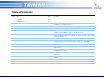
Table of Contents Section Title Page Features 3 Specifications 4 Description 1 Equipment Installation 5 2 Configuring the TRIMAR 9 Basic procedures for working with the TRIMAR web-based administration utility. 3 Information Tab 11 An explanation on how to obtain the current operational status of the TRIMAR.
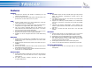
Features GENERAL: Enterprise-class wireless LAN capable of supporting up to 48 infrastructure stations/users. Power-Over-Ethernet system (POE) allows individual radios to be powered over the same cable used to carry data. SSID: Supports multiple SSIDs. Up to eight simultaneous virtual APs can be supported by each TRIMAR radio. Each SSID can have its own individual security and authentication configuration that supports WEP, WPA or WPA2 (802.11i).
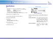
Specifications TRIMAR FCC label: • RF O O O O O O O Operating Frequency Range: 2.4 –2.4835 GHz, 5.15 – 5.85 GHz Data Rate: 54, 48, 36, 24, 18,12, 11, 9, 6, 5.5, 2 and 1 Mbps Turbo mode: 108 Mbps Modulation: OFDM/CCK/DQPSK/DBPSK Antenna Connector: Type N Female Transmission Power: 14dBm typical at antenna port Receiving Sensitivity: 65dBm @ 54 Mbps, -80dBm @11Mbps, at 10-5 BER • Network Interface: 10/100BaseT RJ-45 Figure 1: TRIMAR FCC label • Security: WPA, WPA2, WEP, TKIP, AES, 802.
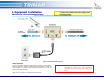
1. Equipment Installation Tip: Manufacturer’s Recommended Practices Place a UPS battery back-up unit or as a minimum, a surge protector between the power supply outlet and AC-DC adapter. Applying Power and network connections to your TRIMAR Radio Figure 2: Hooking up the DC-Injector Safety Statement: Use only the power adapter provided with this product or other Pegasus Wireless Corporation authorized replacement power adapter.
Equipment Installation (.. /continued) Installing the TRIMAR Radio HOW TO RESET THE RADIO TO FACTORY DEFAULTS: Should it become necessary to do a hardware reset of the TRIMAR AP to factory default settings, follow the steps below. Refer to Figure 3 for the location of the reset button: 1. 2. 3. 4. 5. Unscrew and remove the cable cover and gently pull assembly away from the main case. To reset the unit the radio needs to be powered.
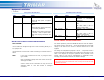
Equipment Installation (.. /continued) DC-Injector LED indicators LED Power Color Amber Network Amber State OFF when there is no power. Steady ON when power is supplied to the unit. OFF when network connection is absent. Steady ON when network connection is successfully established. BLINKING if the network connection is unstable – check or replace cable; make sure all plug connections are snug.
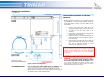
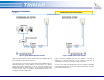
Equipment Installation Tip: (.. /continued) Always test all equipment at the workbench before installing them at their final positions. Example Installations Figure 4: Typical TRIMAR deployment schematic Figure 5: TRIMAR repeater mode schematic Figure 4 above illustrates a common wiring scheme for a TRIMAR radio unit that is physically connected to the network. Figure 5 illustrates a TRIMAR radio used as a repeater.
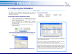
2. Configuring the TRIMAR AP Basic Procedure The TRIMAR AP uses a web-based administration utility. To access this utility you will need to use Microsoft ® Internet Explorer, Mozilla Firefox or a compatible web-browser. Accessing the web-based administration utility: 1. 2. 3. Connect a PC either directly to the TRIMAR radio. If the radio is already configured for operation on an established network, connect to it via a network route.
Configuring the TRIMAR AP (.. /continued) Navigating and using the web-based administration utility The different pages of the web-based administration utility can be accessed by clicking on the buttons located on the left side of the web-based administration screen. Make all the desired changes under each tab and “Save” the changes before moving to the next tab. If the only changes that are being made are under the same tab, simply click “Reboot” to apply the settings.
3. Information Tab This is the “home page” of the TRIMAR’s web-based administration utility. It will be displayed when the utility is first accessed and whenever the TRIMAR AP has been rebooted after configuration changes have been made. The information on this page gives various readings polled directly from the TRIMAR AP. This data is a “capture” of its current operational status. Note that it may be necessary to refresh the page to re-poll the TRIMAR AP to update the displayed information.
4. Administration Tab Device Control: (See Figure 12) Reboot: Reset Configuration: Clicking on this button causes the unit to be rebooted. This is normally used in conjunction with configuring the TRIMAR AP. Clicking on this button causes the unit to reboot and will reset the unit’s configuration back to its original factory default settings. Use with caution as this will cause all custom user settings to be lost.
Administration Tab (.. /continued) IP settings: (See Figure 15) These controls are used to assign the TRIMAR AP with its custom IP addressing scheme. IP Addressing Mode: Static – select this control if a static/fixed IP address is to be used. DHCP – select this control if the IP address is to be assigned by an external DHCP server. Default IP address: Use this field to enter a valid IP address. Default subnet mask: Use this field to enter a valid subnet mask.
Administration Tab (.. /continued) SNMP Setting: (See Figure 17) These controls are used to enable SNMP control of the TRIMAR AP. SNMP enabled: Check this box management. to enable SNMP SNMP server IP address: This field is used to direct the TRIMAR AP to the network location of the SNMP server.
5. Basic Wireless Tab (See Figure 19) Wireless On/Off: This control allows a TRIMAR AP to be switched On or Off. This is not the same as an on/off switch. It simply allows the wireless functions of the radio to be switched off for maintenance or other contingencies. Visible SSID: The TRIMAR AP can support up to eight SSIDs simultaneously. Only one can be visible. This control is used to specify which SSID is to be made visible.
Basic Wireless Tab (.. /continued) (See Figure 19 on previous page) Auto Channel Select: This control allows the TRIMAR AP to automatically select what it determines is the best channel to use. This occurs during the radio’s boot up process. The channel it selects can be seen under the Information Tab. Channel: This control is used to set a channel manually. Channels cannot be manually set when Super modes are enabled or if the radio has been set to automatically select a channel when it boots up.
6. Advanced Tab (See Figure 20) Fragmentation Threshold: This determines the maximum size of a data package in bytes. Packages larger than the set value will be broken up for transmission purposes. Reducing the package size in a noisy wireless environment should maintain overall performance. Factory default: 3200 bytes RTS/CTS Threshold: Reducing the preset value will enable RTS/CTS and may maintain overall performance in a noisy wireless environment.
Advanced Tab (.. /continued) (See on previous page Figure 20) DTIM Interval: This value determines the frequency when the radio will send broadcast/multicast packets to stations in power save mode. This function is associated with the Beacon Period. Factory default: 1 (each beacon period or once every 100 milliseconds) 802.11d Global Harmonization control. Factory default: Disabled. Transmit Power: This controls the power output permitted to the antenna.
7. SSID Admin Tab SSID CONTROLS (See Figure 21) SSID #: Selecting an item in this dropdown menu allows configuration to be performed on the SSID selected. All the settings on this page are the exclusive properties of the selected SSID. Note the SSID number at the top of the frame – this indicates exactly which of the eight-supported SSID is currently being configured. The TRIMAR AP is designed to be able to support up to 8 SSIDs simultaneously.
SSID Admin Tab (.. /continued) WPA configuration (See Figure 22) Each configured SSID can support its own unique WPA configuration, which it does not need to share with the other SSIDs in the configuration set. WPA Enable: Check this box if WPA is to be used to secure this SSID’s wireless access and transmissions. WPA Mode: Select the desired WPA mode.
SSID Admin Tab (.. /continued) 802.1X configuration (See Figure 23) If WPA is used in conjunction with a RADIUS Server, these controls are used to activate this service. The TRIMAR AP can support two RADIUS servers. The first RADIUS server entered is the “preferred” server, and the second RADIUS server entered is the “backup” server that will be accessed if, for whatever reason, the first server cannot be located. Authentication Timeout: By default the 802.
SSID Admin Tab (.. /continued) WEP configuration (See Figure 24) The same WEP keys are used by all SSIDs using WEP encryption on the TRIMAR AP. TRIMAR APs deployed in WDS mode are limited to using WEP. Enable WEP: Check this box if the selected SSID will implement WEP as a component of its security policy. Figure 24: WEP configuration VLAN configuration (See Figure 25) Each of the TRIMAR AP’s eight SSIDs can support a separate VLAN.
8. WEP Security Tab WEP configuration (See Figure 26) The WEP settings configured under this tab are shared by all SSIDs configured to use WEP. TRIMAR APs used in WDS mode are limited to using WEP encryption only. Enable WEP: Check this box to enable WEP. Each SSID using WEP must also have its WEP configuration box checked. Default WEP Key: Select the default WEP transmission key (1-4). The radio will use this key for transmissions only.
9. Access Control Tab Access Control (See Figure 27) These controls allow administrators to specifically allow stations to associate with the access point. This is accomplished by entering the allowed stations’ unique MAC addresses into the MAC address fields. Stations whose MAC addresses are not entered into the list will not be able to authenticate with the TRIMAR AP. Access Control is also commonly referred to as MAC address filtering.
10. WDS Tab For load-balance management and other network administrative functions, use a TRIMAR Controller to manage all aspects of a TRIMAR WDS mesh. Wireless Distribution System (See Figure 28) WDS is one of the most important TRIMAR AP features. It allows TRIMAR APs to communicate with each other as well as other makes of APs to create radial and linear wireless meshes. Each TRIMAR AP can be linked with up to six other WDS capable APs.
WDS Tab (.. /continued) WDS neighbor table (See Figure 29) This display reports on the radios that are a part of the same mesh and includes information such as the associating units MAC address, SSID and the wireless signal quality. WDS table: This button refreshes the display. Figure 29: WDS Table PEGASUS WIRELESS CORPORATION TRIMAR TECHNICAL MANUAL Version 1.
11. DHCP Server Tab DHCP Server Configuration (See Figure 30 and Figure 31) The TRIMAR AP can be configured to function as a DHCP server. To use this feature, since the TRIMAR AP can only issue IP addresses within its own IP subnet, the TRIMAR AP must be given an IP address in the same IP subnet as the IP addresses it will be assigning. DHCP server: Check this box to enable the TRIMAR AP’s DHCP functions.
12. Stations Tab Stations (See Figure 32) The stations tab display shows information about all stations that have associated with the TRIMAR AP. Information polled from the associated stations include the individual stations’ MAC addresses as well as the number of packets sent and received. Figure 32: Associated stations display PEGASUS WIRELESS CORPORATION TRIMAR TECHNICAL MANUAL Version 1.
13. Save Tab Save Configuration (See Figure 33, Figure 34 and Figure 35) A TRIMAR AP’s configuration can be saved to a template and reapplied to other TRIMAR APs. This feature makes it easy to configure and deploy multiple units quickly and without having to re-type the configuration information into every unit. In most instances, all that needs to be changed are the individual unit’s IP addresses and adjustments to the WDS settings so that units do not refer to themselves.
Save Tab (.. /continued) Uploading a template (See Figure 36) To upload a template file into a TRIMAR AP open the settings.htm file using a web-browser. Target AP: Enter the IP address of the TRIMAR AP to which the template is to be applied. Upload Settings: Click on this button to upload the template file. This can take several minutes. Once the template has fully uploaded, the webbased administration utility for the target TRIMAR AP will be automatically started.
14. Help Tab Contact our Technical Support department for additional technical assistance for configuring and deploying your TRIMAR AP. OTC Wireless Technical Support Department can be contacted by either email, phone or the web-mail form on the Pegasus Wireless Corporation web site: Email: Website: Phone: Fax: support@otcwireless.com http://www.otcwireless.com/support/technicalsupport.
Appendix Limited Warranty FCC Rules and Regulations - Part 15 The seller warrants to the end user (“Customer”) that this product will be free from defects in workmanship and materials, under normal use and service, for one (1) year from the date of purchase. The seller’s sole obligation under this express warranty shall be, at the seller’s option and expense, to repair the defective product or part, deliver to Customer an equivalent product or part to replace the defective item.