
Owner manual


14
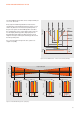
WIRING AND CONFIGURATION OF THE ECG
4.2.2. Parameter setting via 3DIM Tool
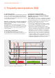
The StepDIM operation is defi ned by three parameters:
power-on level, dim level and dim fade time. In addition,
StepDIM can be operated according to two different signal
logics.
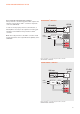
The SD control states HIGH and LOW refer to the different
output power levels of the ECG. By default, LOW means
that the ECG provides the power-on level and HIGH
means that the ECG provides the dim level (see fi gure 19).
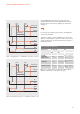
Via the 3DIM Tool, it is possible to select the “StepDIM
inverse/DALI” mode, which reverses the logical relation
between the SD control state and the ECG output power
level (see fi gure 20).
The power-on level and dim level are set as a percentage
of the nominal output current or power (depending on the
output type of the ECG).
Note: The power-on level and dim level depend on the
nearest admissible DALI
®
value. Setting an intermediate
value results in a rounding to the nearest admissible value
(see table below).
Table 4: StepDIM parameters
Parameter Description
Power-on level Output power level of the ECG
(in % of the nominal value of the ECG/
lamp combination) after switch-on via
the mains.
Dim level* Output power level of the ECG
(in % of the nominal value of the ECG/
lamp combination) after the SD state
has changed.
Dim fade time** Transition time between power-on level
and dim level.
StepDIM signal logic
StepDIM polarity The polarity of the input signal used
for dim activation can be changed →
“StepDIM inverse/DALI” mode.
Table 5: DALI
®
logarithmic dimming curve*
8-bit arc power level Arc power (%) 3DIM level (%)
254 100.000 100
253 97.307 97
252 94.686 95
251 92.135 92
250 89.654 90
249 87.239 87
248 84.889 85
247 82.603 83
246 80.378 80
245 78.213 78
………
* Please note that the dim level is also referred to as “Dim level 1”
in the 3DIM Tool.
** Can only be set for OPTOTRONIC
®
3DIM ECGs.
* See IEC 62386-102, table 9.1.