2015-12-14 SMT Multi TOPLED Version 1.
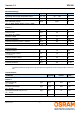
Version 1.3 SFH 331 Maximum Ratings Parameter Symbol Values Unit Operating and storage temperature range Top; Tstg -40 ... 100 °C Junction temperature Tj 100 °C ESD withstand voltage (acc. to ANSI/ ESDA/ JEDEC JS-001 - HBM) VESD 2000 V Emitter 1 Forward current IF 30 mA Surge current (tp ≤ 10 µs, D = 0.005) IFSM 0.
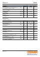
Version 1.3 SFH 331 Parameter Symbol Values Unit Rise and fall times of Ie ( 10% and 90% of Ie max) (IC = 100 mA, tp = 10 µs, RL = 50 Ω) (typ) tr / tf 300 / 150 ns Capacitance (VR = 0 V, f = 1 MHz) (typ) C0 12 pF Forward voltage (IF = 10 mA) (typ (max)) VF 2 (≤ 2.6) V Reverse current (VR = 5 V) (typ (max)) IR 0.01 (≤ 10) µA Luminous intensity (IF = 10 mA) (min) IV 6 (4 ... 12.5) mcd Wavelength of max.
Version 1.3 SFH 331 Relative Spectral Emission 2) page 16 (typ) Irel = f(λ), TA = 25 °C, IF = 20 mA, V(λ) = Standard Eye Response Curve OHL02350 100 % Φ rel 80 Vλ 60 40 20 super-red 0 400 450 500 550 600 650 700 nm λ Relative Luminous Intensity 2) page 16 Iv / Iv(10 mA) = f(IF), TA = 25 °C Max.
Version 1.3 SFH 331 Forward Current 2) page 16 IF = f(VF), TA = 25 °C Permissible Pulse Handling Capability IF = f(tp), T A = 25 °C, duty cycle D = parameter OHL02351 10 2 OHL01686 10 3 Ι F mA IF D= mA tP tP IF T T D = 0.005 0.01 0.02 0.05 0.1 10 1 5 10 2 0.2 super-red 5 10 0 5 0.5 DC 10 -1 1.0 1.4 1.8 2.2 2.6 10 1 -5 10 3.0 V 3.
Version 1.3 SFH 331 Forward Voltage 2) page 16 VF = f(TA), IF = 10 mA Relative Luminous Intensity 2) page 16 Iv / Iv(25 °C) = f(TA), IF = 10 mA OHL02106 2.4 VF OHL02150 2.0 IV V I V (25 ˚C) 2.2 2.0 1.6 1.2 yellow green green super-red orange yellow 1.8 0.8 pure-green pure-green 1.6 1.4 0.4 0 20 40 60 0.
Version 1.3 SFH 331 Diagrams Phototransistor Relative Spectral Sensitivity 2) page 16 Srel = f(λ) Srel Photocurrent 2) page 16 IPCE = f(Ee), VCE = 5 V OHF01924 10 3 µA OHF00207 100 % Ι PCE 80 10 2 70 60 4 3 2 10 1 50 40 30 10 0 20 10 0 400 500 600 700 800 900 10 -1 -3 10 nm 1100 λ Photocurrent 2) page 16 IPCE / IPCE(25°C) = f(TA), VCE = 5 V OHF01529 Ι PCE mW 1 2 cm Ι PCE 10 0 mW/cm 2 Ee Photocurrent 2) page 16 IPCE = f(VCE), Ee = Parameter 10 0 mA 10 -2 OHF01524 1.
Version 1.3 SFH 331 Dark Current 2) page 16 ICEO = f(VCE), E = 0 Dark Current 2) page 16 ICEO = f(TA), VCE = 5 V, E = 0 OHF01527 10 1 nA Ι CEO Ι CEO 10 0 10 2 10 -1 10 1 10 -2 10 0 10 -3 OHF01530 10 3 nA 0 5 10 15 20 25 10 -1 -25 30 V 35 V CE Collector-Emitter Capacitance 2) page 16 CCE = f(VCE), f = 1 MHz, E = 0 25 50 75 ˚C 100 TA Power Consumption Ptot = f(TA) OHF01528 5.0 0 OHF00871 200 C CE pF mW P tot 4.0 160 3.5 120 3.0 2.5 80 2.0 1.5 1.0 40 0.
Version 1.3 SFH 331 Emitter Radiation Characteristics / Phototransistor Directional Characteristics 2) page 16 Irel = f(ϕ) / Srel = f(ϕ) 40˚ 30˚ 20˚ 10˚ 0˚ ϕ 50˚ OHL01660 1.0 0.8 0.6 60˚ 0.4 70˚ 0.2 80˚ 0 90˚ 100˚ 1.0 0.8 0.6 0.4 0˚ 20˚ 40˚ 60˚ 80˚ Package Outline 3.0 (0.118) 2.6 (0.102) 2.3 (0.091) 2.1 (0.083) C E 0.1 (0.004) typ 4 Package marking Emission color : super-red (SFH 331) 0.5 (0.020) C 3.7 (0.146) 3.3 (0.130) 3 A 1 0.9 (0.035) 0.7 (0.028) 1.1 (0.043) 2 1.
Version 1.3 SFH 331 Approximate Weight: 34 mg Recommended Solder Pad Dimensions in mm. Reflow Soldering Profile Product complies to MSL Level 2 acc. to JEDEC J-STD-020D.
Version 1.
Version 1.3 SFH 331 Tape and Reel 8 mm tape with 2000 pcs. on ∅ 180 mm reel, 8000 pcs. on ∅ 330 mm reel W1 D0 P0 A N F W E 13.0 ±0.25 P2 Label P1 Direction of unreeling Direction of unreeling W2 Leader: min. 400 mm * Trailer: min. 160 mm * *) Dimensions acc. to IEC 60286-3; EIA 481-D OHAY0324 Tape dimensions [mm] Tape dim ensions in m m W P0 P1 P2 D0 E F 8 + 0.3 / -0.1 4 ± 0.1 2 ± 0.05 or 4 ± 0.1 2 ± 0.05 1.5 ± 0.1 1.75 ± 0.1 3.5 ± 0.
Version 1.3 SFH 331 Barcode-Product-Label (BPL) OSRAM Opto EX A RoHS Compliant (6P) BATCH NO: 1234567890 (1T) LOT NO: 1234567890 BIN1: XX-XX-X-XXX-X LX XXXX Semiconductors MP ML Temp ST X XXX °C X (9D) D/C: 1234 Pack: RXX LE DEMY XXX X_X123_1234.1234 X (X) PROD NO: 123456789(Q)QTY: 9999 (G) GROUP: XX-XX-X-X OHA04563 Dry Packing Process and Materials Moisture-sensitive label or print L VE el see lab e LE If nk, bla cod bar . H) y (R .
Version 1.
Version 1.3 SFH 331 Disclaimer Language english will prevail in case of any discrepancies or deviations between the two language wordings. Attention please! The information describes the type of component and shall not be considered as assured characteristics. Terms of delivery and rights to change design reserved. Due to technical requirements components may contain dangerous substances. For information on the types in question please contact our Sales Organization.
Version 1.3 SFH 331 Glossary 1) Thermal resistance: junction -ambient, mounted on PC-board (FR4), padsize 16 mm2 each 2) Typical Values: Due to the special conditions of the manufacturing processes of LED, the typical data or calculated correlations of technical parameters can only reflect statistical figures. These do not necessarily correspond to the actual parameters of each single product, which could differ from the typical data and calculated correlations or the typical characteristic line.
Version 1.3 SFH 331 Published by OSRAM Opto Semiconductors GmbH Leibnizstraße 4, D-93055 Regensburg www.osram-os.com © All Rights Reserved.