
Data Sheet

R
L
= 1 kΩ
V
CC
C
L
= 50 pF
(See Note 1)
t
buf
t
icr
t
sth
t
sds
t
sdh
t
icf
t
icr
t
scl
t
sch
t
sts
t
vd(ACK)
or t
vdL
t
vdH
0.3 × V
CC
Stop
Condition
t
sps
Repeat
Start
Condition
Start or Repeat
Start Condition
SCL
SDA
Start
Condition
(S)
Address
Bit 7
(MSB)
Data
Bit 0
(LSB)
Stop
Condition
(P)
Two Bytes for Complete
Device Programming
I
2
C PORT LOAD CONFIGURATION
VOLTAGE WAVEFORMS
t
icf
Stop
Condition
(P)
t
sp
DUT
SDn, SCn
0.7 × V
CC
0.3 × V
CC
0.7 × V
CC
R/W
Bit 0
(LSB)
ACK
(A)
Data
Bit 7
(MSB)
Address
Bit 1
Address
Bit 6
ACK
(A)
BYTE DESCRIPTION
I
2
C address + R/W
Control register data
1
2
Copyright © 2016, Texas Instruments Incorporated
8
PCA9546A
SCPS148G –OCTOBER 2005–REVISED MAY 2016
www.ti.com
Product Folder Links: PCA9546A
Submit Documentation Feedback Copyright © 2005–2016, Texas Instruments Incorporated
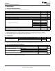
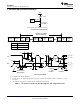
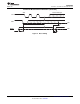
7 Parameter Measurement Information
(1) C
L
includes probe and jig capacitance.
(2) All input pulses are supplied by generators having the following characteristics: PRR ≤ 10 MHz, Z
O
= 50 Ω,
t
r
/t
f
≤ 30 ns.
(3) The outputs are measured one at a time, with one transition per measurement.
Figure 1. I
2
C Interface Load Circuit, Byte Descriptions, and Voltage Waveforms