
Data Sheet

SDA
SCL
Data Line
Stable;
Data Valid
Change
of Data
Allowed
11
PCA9546A
www.ti.com
SCPS148G –OCTOBER 2005–REVISED MAY 2016
Product Folder Links: PCA9546A
Submit Documentation FeedbackCopyright © 2005–2016, Texas Instruments Incorporated
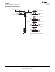
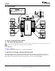
8.3 Feature Description
The PCA9546A is a 4-channel, bidirectional translating switch for I
2
C buses that supports Standard-Mode (100
kHz) and Fast-Mode (400 kHz) operation. The PCA9546A features I
2
C control using a single 8-bit control register
in which the four least significant bits control the enabling and disabling of the 4 switch channels of I
2
C data flow.
Depending on the application, voltage translation of the I
2
C bus can also be achieved using the PCA9546A to
allow 1.8-V, 2.5-V, or 3.3-V parts to communicate with 5-V parts. Additionally, in the event that communication on
the I
2
C bus enters a fault state, the PCA9546A can be reset to resume normal operation using the RESET pin
feature or by a power-on reset which results from cycling power to the device.
8.4 Device Functional Modes
8.4.1 RESET Input
The RESET input is an active-low signal that may be used to recover from a bus-fault condition. When this signal
is asserted low for a minimum of t
WL
, the PCA9546A resets its registers and I
2
C state machine and deselects all
channels. The RESET input must be connected to V
CC
through a pull-up resistor.
8.4.1.1 RESET Errata
If RESET voltage set higher than V
CC
, current will flow from RESET pin to V
CC
pin.
System Impact
V
CC
will be pulled above its regular voltage level
System Workaround
Design such that RESET voltage is same or lower than V
CC
8.4.2 Power-On Reset
When power is applied to V
CC
, an internal power-on reset holds the PCA9546A in a reset condition until V
CC
has
reached V
POR
. At this point, the reset condition is released, and the PCA9546A registers and I
2
C state machine
are initialized to their default states, all zeroes, causing all the channels to be deselected. Thereafter, V
CC
must
be lowered below V
POR
to reset the device.
See the Power-On Reset Errata section.
8.5 Programming
8.5.1 I
2
C Interface
The I
2
C bus is for two-way two-line communication between different ICs or modules. The two lines are a serial
data line (SDA) and a serial clock line (SCL). Both lines must be connected to a positive supply via a pull-up
resistor when connected to the output stages of a device. Data transfer can be initiated only when the bus is not
busy.
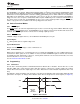
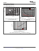
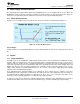
One data bit is transferred during each clock pulse. The data on the SDA line must remain stable during the high
period of the clock pulse, as changes in the data line at this time are interpreted as control signals (see Figure 3).
Figure 3. Bit Transfer