
Installation Instructions

PREPARATION
1. Shut o the power at the circuit breaker and remove existing xture, including the crossbar.
2. Carefully unpack your new xture and lay out all the parts on a clear area. Be careful not to lose any sm
all parts necessary for
installation.
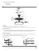
MOUNTING THE FIXTURE (Fig. 1)
3. Remove the mounting screw (E) from the mounting back plate.
4. Drill holes in the wall aligned with the key holes located in the mounting back plate, insert the plastic anchors (D).
5. Secure the mounting plate to the junction box using junction box screws (B), fasten it to the wall using wood screws (C). The side of
the mounting back plate marked “GND” must face out.
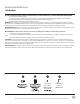
CONNECTING THE WIRES (Fig. 2)
6. Connect the driver input/output wires to junction box wires as shown in
Fig. 2, making sure that all wire connectors (A) are secured. If your outlet
box has a green or bare copper ground wire, connect the xture’s ground
wire to it. Otherwise, connect the xture’s ground wire directly to the
back plate using the green screw provided. After wires are connected,
tuck them carefully inside the junction box.
* Requires Driver to be recessed within the junction box.
COMPLETING THE INSTALLATION (Fig. 1)
7. Secure the xture to the mounting back plate using the mounting screw (E).
4 1/8”
1 3/4”
Fixture Wires
Black or
Smooth
Fixture Wires
White or
Ribbed
Fixture Wires
Bare wire
(Ground)
House Wires
Black
(Hot)
House Wires
White
(Neutral)
House Wires
Green or Bare Copper
(Ground)
Fig.2 Wiring
Junction Box
Wire Connector
Driverw-Y
w8Yw)
Plastic Anchor
Mounting #BDLPlate
Wood Screw
Mounting Screw
'JYUVSF
A
D
C
E
Ground Wire Screw
/;:;+'ULYHU
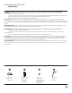
3. Remove the mounting screw (C) from the fixture.
5. Secure the mounting back plate to the junction box using junction box
screws (B).The side of the mounting back plate marked “GND” must face out.
6. Secure the canopy to the mounting plate using the mounting screw (C).
4. Connect the Driver’s input wires to junction box wires as shown in Fig. 2, making sure that all wire connectors (A) are secured.
If your outlet box has a green or bare copper ground wire, connect the fixture’s ground wire to it. Otherwise, connect the fixture’s
ground wire directly to the back plate using the green screw provided. After wires are connected, tuck them carefully inside the junction box.
CONNECTING THE WIRES (Fig. 2)
1.
Shut o
ff the power at the circuit breaker and rem
ove existing fixture, including the crossbar.
2. Carefully unpack your new fixture and lay out all the parts on a clear area. Be careful not lose any small parts necessary for installation.
PREPARATION
MOUNTING THE FIXTURE(Fig.1)
7. There is optional metal clip in hardware bag, remove the screw (D) to
replace the plastic clip, secure the metal clip with screw (D).
Fixture Wires
Black or
Smooth
Fixture Wires
White or
Ribbed
Fixture Wires
Bare wire
(Ground)
House Wires
Black
(Hot)
House Wires
White
(Neutral)
House Wires
Green or Bare Copper
(Ground)
Fig.2 Wiring
10 5/16"
3. Remove the mounting screw (C) from the canopy.
6. Secure the mounting back plate to the junction box using junction box
screws (B).The side of the mounting back plate marked “GND” must face out.
4. Adjust the fixture wire length by pushing the cable gripper on the canopy and pulling the wire as desired. Make sure the wires are the
same length.
5. Connect the Driver’s input wires to junction box wires as shown in Fig. 2, making sure that all wire connectors (A) are secured. If your
outlet box has a green or bare copper ground wire, connect the fixture’s
ground wire to it. Otherwise, connect the fixture’s ground wire directly to
the back plate using the green screw provided. After wires are connected,
tuck them carefully inside the junction box.
CONNECTING THE WIRES (Fig. 2)
1.
Shut o
ff the power at the circuit breaker and rem
ove existing fixture, including the crossbar.
2. Carefully unpack your new fixture and lay out all the parts on a clear area. Be careful not lose any small parts necessary for installation.
PREPARATION
MOUNTING THE FIXTURE(Fig.1)
Fixture Wires
Black or
Smooth
Fixture Wires
White or
Ribbed
Fixture Wires
Bare wire
(Ground)
House Wires
Black
(Hot)
House Wires
White
(Neutral)
House Wires
Green or Bare Copper
(Ground)
Fig.2 Wiring
Ground Wire Screw
Plate
7. Hook the safety cord to the mounting plate.
8. Secure the canopy to the mounting plate using the mounting screw (C).
Junction Box
Wire Connector
$
0RXQWLQJ3ODWH
&
$OOHQ6FUHZ
Canopy
Junction Box Screw
Mounting Screw
Input Wires
%
'
$OOHQ :UHQFK
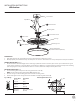
4. Secure mounting plate to the junction box using junction box screws (B).The side of the mounting plate marked “GND” must face out.
5. Place the canopy over the mounting plate and secure with mounting screws.
3. Connect the fixture wires with supply wires as shown in Fig. 2, making sure all wire connector(A) are secured. If your outlet box has a
green or bare copper ground wire, connect the fixture’s ground wire to it. Otherwise, connect the fixture’s ground wire directly to the
mounting plate using the green screw provided. After all wires are connected, tuck them carefully inside the junction box.
CONNECTING THE WIRES (Fig. 2)
1. Shut off the power at the circuit breaker and remove existing fixture, including the crossbar.
2. Carefully unpack your new fixture and lay out all the parts on a clear area. Be careful not lose any small parts necessary for installation.
PREPARATION
MOUNTING THE FIXTURE (Fig. 1)
6. Twist lock the acrylic shade into the canopy, then lock it with allen screw (C) using allen wench (D).
Fixture Wires
Black or
Smooth
Fixture Wires
White or
Ribbed
Fixture Wires
Bare wire
(Ground)
House Wires
Black
(Hot)
House Wires
White
(Neutral)
House Wires
Green or Bare Copper
(Ground)
Fig.2 Wiring
Ø4"
1 3/4”
1 3/8”
FIG.1
INSTALLATION INSTRUCTIONS
LED Outdoor
We retain the right to modify the design of our products at any time as part of the company's continuous improvement program.
Mounting Plate Dimensions