
Installation Instruction
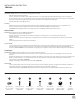
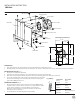

FIG.1
Screw
Silicon Gasket
Knurled Nut
Wire
Connector
Junction Box Screw
Plastic Anchor
Junction Box
Ground Wire
Mounting Plate
Wood Screw
G1
E1
F1
A1
B1
C1
D1
Fixture Wires
Black or
Smooth
Fixture Wires
White or
Ribbed
Fixture Wires
Bare wire
(Ground)
House Wires
Black
(Hot)
House Wires
White
(Neutral)
House Wires
Green or Bare Copper
(Ground)
Fig. 2 Wiring
PREPARATION
1. Shut o the power at the circuit breaker and remove existing xture, including the crossbar.
2. Carefully unpack your new xture and lay out all the parts on a clear area. Be careful not to lose any small parts necessary for installation.
MOUNTING THE FIXTURE (Fig. 1)
3. Remove the screw (G1) from the xture.
4. Insert the outer glass into the xture, secure it with knurled nut (F1) and silicon gasket (E1).
5. Drill a hole in the wall aligned with the key holes located in the mounting plate, insert the plastic anchor (C1).
6. Secure the mounting plate to the junction box using junction box screws (B1),
fasten it to the wall using wood screw (D1). The side of the mounting back
plate marked “GND” must face out.
CONNECTING THE WIRES (Fig. 2)
7. Connect the xture wires to junction box wires as shown in Fig. 2, making
sure that all wire connectors (A1) are secured. If your outlet box has a green
or bare copper ground wire, connect the xture’s ground wire to it.
Otherwise, connect the xture’s ground wire directly to the back plate
using the green screw provided.
8. Secure the xture to the mounting plate using screw (G1).
Ø
3 1/2"
Ø
2 3/4"
Mounting Plate Dimensions
5 1/8"
2 1/2"
8 1/8"
5 7/8"
1 3/4"
1 3/8"
4"
INSTALLATION INSTRUCTION
LED Bath
Inner Glass
Outer Glass
2