
Installation Instruction
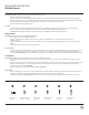
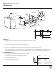

FIG.1
Mounting Screw
Ground Wire Screw
Ground Wire
Junction Box
Wire Connector
Plastic Anchor
Back Plate
Fixture Screw
Junction Box Screw
Wood Screw
Mounting Plate
DriverMetal Shade
D1
A1
F1
C1
B1
E1
Fixture Wires
Black or
Smooth
Fixture Wires
White or
Ribbed
Fixture Wires
Bare wire
(Ground)
House Wires
Black
(Hot)
House Wires
White
(Neutral)
House Wires
Green or Bare Copper
(Ground)
Fig.2 Wiring
PREPARATION
1. Shut o the power at the circuit breaker and remove existing xture, including the crossbar.
2. Carefully unpack your new xture and lay out all the parts on a clear area. Be careful not to lose any small parts necessary for installation.
INSTALLATION (Fig. 1)
3. Remove the mounting screw (D1) and metal shade from the back plate.
4. Remove the xture screw (C1) and mounting plate from the back plate.
5. Drill a hole in the wall aligned with the key-hole located in the mounting plate, insert the plastic anchor (F1).
6. Connect the Driver’s input/output wires to junction box wires as shown in Fig. 2, making sure that all wire connectors (A1) are secured.
If your outlet box has a green or bare copper ground wire, connect the xture’s ground wire to it. Otherwise, connect the xture’s ground
wire directly to the back plate using the green screw provided. After wires are connected, tuck them carefully inside the junction box.
MOUNTING THE FIXTURE (Fig. 1)
7. Secure the back plate to the junction box using junction box screws (B1).
Fasten the mounting plate to the wall using the wood screw (E1).
The side of the mounting back plate marked “GND” must face out.
8. Place the mounting plate to the back plate and
Secure it with xture screw (C1).
9. Place the metal shade to the back plate,
secure it with mounting screw (D1)
Back Plate Dimensions
11 2”
5w”
5w”
1w”
3”
12”
INSTALLATION INSTRUCTION
LED Wall Sconce
2