
Installation Instruction


3
PREPARATION
1. Shut o the power at the circuit breaker and remove existing xture, including the crossbar.
2. Carefully unpack your new xture and lay out all the parts on a clear area. Be careful not to lose any small parts necessary for installation.
INSTALLATION
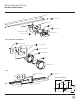
MOUNT ON SWITCH BOX (Fig. 1)
3. Remove the mounting screw (B1) from the xture.
4. Connect the driver (G1) input wire to switch box wires as shown in Fig. 4, making sure that all wire connectors (A1) are secured.
If your outlet box has a green or bare cooper ground wire, connect the xture’s ground wire to it. Otherwise, connect the xture’s ground
wire directly to the back plate using the green screw provided. After wires are connected, tuck them carefully inside the switch box.
*Requires Driver to be recessed within the switch box.
5. Secure the mounting plate to the switch box using the junction box screw (C1). The side of the mounting plate marked “GND” must face out.
6. The back plate location for this xture is adjustable. First loosen both adjustable nuts by turning counterclockwise. Second adjust the
back plate to your desired location. Third, pull and tighten the electrical wire. Lastly, secure the back plate by turning both adjustable
nuts clockwise.
7. Place the xture over the mounting plate, and secure it with mounting screw (B1).
OR
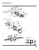
MOUNT ON JUNCTION BOX (Fig. 2)
3. Remove the mounting screw (B1) from the xture.
4. Connect the driver (G1) input wire to junction box wires as shown in Fig. 4, making sure that all wire connectors (A1) are secured.
If your outlet box has a green or bare cooper ground wire, connect the xture’s ground wire to it. Otherwise, connect the xture’s ground
wire directly to the back plate using the green screw provided. After wires are connected, tuck them carefully inside the switch box.
*Requires driver to be recessed within the junction box.
5. Secure the mounting ring to the junction box using the junction box screw (C1). Make sure the two holes (Spacing 2-3/4”) are horizontal as
shown in Fig. 2. The side of the mounting plate marked “GND” must face out.
6. Secure the mounting plate and conversion plate to the mounting ring with assembly screw (F1).
7. The back plate location for this xture is adjustable. First loosen both adjustable nuts by turning counterclockwise. Second adjust the
back plate to your desired location. Third, pull and tighten the electrical wire. Lastly, secure the back plate by turning both adjustable
nuts clockwise.
8. Place the xture over the mounting plate, and secure it with mounting screw (B1).
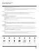
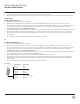
Fixture Wires
Black or
Smooth
Fixture Wires
White or
Ribbed
Fixture Wires
Bare wire
(Ground)
House Wires
Black
(Hot)
House Wires
White
(Neutral)
House Wires
Green or Bare Copper
(Ground)
Fig. 4 Wiring
INSTALLATION INSTRUCTION
Vanities & Wall Sconce