翔鑫科技股份有份公司 Oro Technology Co.
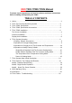
ORO TR01 TPMS TPMS Manual To ensure correct operations and services please read these instructions before installing and operating the TPMS TABLE of CONTENTS 1. 2. 3. 4. 5. Notice………...………………………………………………...……………….……1 TR01 Tire Pressure Monitoring System………………………………………...2 TR01 TPMS Specification…..…….…………………………………...…………2 TR01 TPMS Specification Accessories……………………………..…………..3 TR01 TPMS Installation……………..…………………………………..……….4 Tire Sensor Installation………………………….…………………….…….…......
NOTICE FCC Federal Communications Commission (FCC) Statement This equipment has been tested and found to comply with the limits for a Class B digital device, pursuant to Part 15 of the FCC Rules. These limits are designed to provide reasonable protection against harmful interference in a residential installation. This equipment generates, uses and can radiate radio frequency energy and, if not installed and used in accordance with the instructions, may cause harmful interference to radio communications.
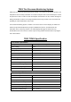
TR01 Tire Pressure Monitoring System ORO-TR01 Tire Pressure Monitoring Systems (TPMS), can monitor and provide tire pressure, tire temperature and car battery information in real time to help the driver control and keep the normal tire pressure in order to reduce the fuel consumption and extend the tire life, and also through the battery information, the driver can change the battery before any incident occurs and reduce the possibility of vehicle breakdown on the roads.
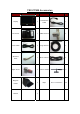
TR01 TPMS Accessories Accessories Pictures QTY Accessories Transmission Picture QTY Display 1 Tire Sensor 7 SMA Terminal 1 Power Cable 1 Long Antenna 1 7 Short Antenna 1 7 Antenna Holder 2 1 Rope 20 Aluminum Valve Nylok Screw Magnetic Holder Manual 1 Cable 1
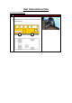
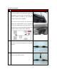
TR01 TPMS INSTALLATION 1. Tire Sensor Installation: Step Operation Process Take off the 7 tires and mark 1~7 for each tire position, No.7 tire is a spare tire.
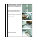
Take off the tire and bleed the air, then. to change to the TPG-Technology TPMS valve, follow the steps: 1. Snap in the valve from the internal edge side of the wheel. 2. Adjust the valve’s angle, and make sure the valve is vertical to the edge of the wheel. 3. Tighten the valve with the nylok screw from the outside of the wheel. b 4. Use the alan key to tighten.
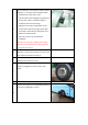
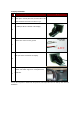
Put the marked No. 1 tire sensor to the tire which is marked No. 1. as step a. photo and follow steps: 1. Install the tire sensor to the valve. 2. Use the nylok screw and tighten up with the tire sensor. (Pls. use the screwdriver which is included to the accessories bag) 3. Adjust the tire sensor’s angle (paste on the c surface of the wheel), then tight up the nylok screw with a torque wrench and please set 5 Newton for torque wrench. 4. Put on the valve’s cap, and finish the installation.
2. Antenna Installation: Step Operation Process 1.The head of long antenna set should pass through the antenna holder and be bundled by rope on the middle place of the real axles. The rest wires of the antenna should be bundle by rope along the chassis to below of the dashboard. 2.The head of short antenna set should pass through the antenna holder and be bundled by a rope on the middle place of the front axles.
3. Display Installation: Step Operation Process Photographs The holder should be fixed on the suitable and a visible place around pilot seat, the front side of the holder should be oriented to the driver’s eye. The transmission wire head should be connected to the SMA port which is behind of the display. b Connect the Red and Green wire to the ACC;Black & White wire connect to the ground. c The USB power cable should be connected to the USB port which is behind of the display.
TR01 Systems Operation 1.Display Signals Description: :Bad Transmission Symbol :Battery Symbol :Tire Deflating Symbol :Abnormal Tire Condition Symbol :Tire Pressure/Temperature Display Unit :Low Battery on Tire Sensor :Pressure Unit。 :Temperature Unit :Tire Position :Tire position shows yellow while shows the tire pressure by the meanwhile. 2.
b. Temperature Display Mode: Display of 7 tires temperature unit only. c. Pressure-Temperature Rotation Display mode: Rotating display of tire pressure and temperature unit. d. Battery Voltage Display Mode: Display of battery voltage unit only. 3. Operation to Change Unit of Tire Pressure and Temperature: ORO-TR01 TPMS displays 2 kinds of pressure units, bar and psi. For temperature, ℃、℉ are the units displayed.
The wireless receiver and display unit shows the standard cold tire pressure. The factory default value (9.0 bar) is shown in blue and the blue b light indicates the ”bar” or pre-selected units (psi). If no modification is needed, press the SET button to enter the next setup mode. NOTE: If the pressure unit is in ”psi” , the display will flash 130. Pressing the MODE button once, will increase the cold tire pressure value by 1 unit; and the unit increases by 0.
unit increases by 0.2 bar with each press of the button, when it has reached 12 bar, pressing the button again will return the system unit to 8.0 bar. NOTE: If the user chooses ”psi” mode, 2 psi will be added with each press of the button, the range for ”psi” is 116 psi~174 psi. Press the SET button to complete the Double d Wheels -Standard Cold Tire Pressure Setting. The system will automatically enter the Tire Temperature-Over Temperature Setting Mode.
Power On Setting Mode Steps Operating Process The system will enter the Power On setting a mode automatically after setting up the Tire Temperature-Over Temperature Setting. The display shown is the factory default for tire pressure value. This is “bar” in blue. If no modification is needed, then press the SET b button to end the set up mode and back to the normal operation mode. NOTE: The system may use other unit for pressure by psi or bar, depending on the region.
TR01 System Alarm Mode Description Mode Warning Condition and Warning Method Warning Situation: When the present tire pressure > 1 .25 x Cold tire std. pressure or tire pressure < 0.75 x Cold tire std. pressure, the system will start warning. (Factory Default for low tire pressure is 9.0 bar, 1 so the systems will start warning when the tire pressure > 11.3 bar or below 6.7 bar.
Warning Situation: When the battery voltage is below than the limit that has been set up. (Factory default for warning is 23.0V) 4 Warning System: The battery symbol will shows red. Warning Situation: When the tire sensor battery level is low. (Suggest to change the sensor as soon as possible) Warning System: The abnormal tire flashes orange, and the low battery symbol flashes red. 5 Warning Situation: When the Monitor run out of initial setting up by factory default.
Warning Situation: When the tire sensor experiences failure when on factory default. Warning System: The affected tire will display a 8 reading of E3. NOTE: 1.The user can press the MODE button continuously for 3 sec. to stop the warning sound. TR01 Reset for Tire Changing and Rotation Upon completion of changing or rotation of tires, the user should also reset the position of the tires on the display unit.
1. Set up for No.1 tire sensor: The tire No.1 symbol will be flashing green on the display. This means the No.1 tire is ready for the set up as per below, Fig.1, in the meantime, the user should deflate the tire pressure rapidly over 0.3 bar/30 kPa or 4 psi within 15 sec. until there is a beep sound, which means the user has completed the set up for No.1 tire. The system will then proceed to tire No.2 sensor setup mode as shown below Fig. 2.. If there is no need to set up tire No.
Fig. 1 Fig. 2 4. Set up for No.4 tire sensor: The tire No.4 symbol will be flashing green on the display. This means the No.4 tire is ready for the set up as per below, Fig.1, in the meantime, the user should deflate the tire pressure rapidly over 0.3 bar/30 kPa or 4 psi within 15 sec. until there is a beep sound, which means the user has completed the set up for No.4 tire. The system will then proceed to tire No.5 sensor setup mode as shown below Fig. 2.. If there is no need to set up tire No.
6. Set up for No.6 tire sensor: The tire No.6 symbol will be flashing green on the display. This means the No.6 tire is ready for the set up as per below, Fig.1, in the meantime, the user should deflate the tire pressure rapidly over 0.3 bar/30 kPa or 4 psi within 15 sec. until there is a beep sound, which means the user has completed the set up for No.6 tire. The system will then proceed to tire No.7 sensor setup mode as shown below Fig. 2.. If there is no need to set up tire No.
mode. 1. No.1 tire sensor replacing: The tire No.1 symbol will be flashing green on the display. This means the No.1 tire is ready for the set up as per below, Fig.1, in the meantime, the user should deflate the tire pressure rapidly over 0.3 bar/30 kPa or 4 psi within 15 sec. until there is a beep sound, which means the user has completed the set up for No.1 tire replacing. The system will then proceed back to the normal display mode. If there is no need to set up tire No.
over 0.3 bar/30 kPa or 4 psi within 15 sec. until there is a beep sound, which means the user has completed the set up for No.3 tire replacing. The system will then proceed back to the normal display mode. If there is no need to set up tire No.3 sensor, just press the SET button to skip this process. The system will then proceed to tire No.4 sensor replacing setup mode as shows on below Fig. 2. Fig. 1 Fig. 2 4. No.4 tire sensor replacing: The tire No.4 symbol will be flashing green on the display.
Fig. 1 Fig. 2 6. No.6 tire sensor replacing: The tire No.6 symbol will be flashing green on the display. This means the No.6 tire is ready for the set up as per below, Fig.1, in the meantime, the user should deflate the tire pressure rapidly over 0.3 bar/30 kPa or 4 psi within 15 sec. until there is a beep sound, which means the user has completed the set up for No.6 tire replacing. The system will then proceed back to the normal display mode. If there is no need to set up tire No.
Fig. 1 Mode 3 :Spare Tire Sensor Rotation The monitor will display No. 3 in blue which means the system is in Mode 3. Choose a tire to be replaced with spare tire starting from No.1 Tire -> No.2 Tire -> No.3 Tire -> No.4 Tire -> No.5 Tire -> No.6 Tire -> No.7 Tire to complete the setup mode 3 and back to the normal operating mode. 1. Spare tire and No.1 tire rotation: The No.1 and No.7 tire symbol will be flashing green on the display. This means the No.1 tire is ready for the set up as per below, Fig.
3. Spare tire and No.3 tire exchange: The No.3 and No.7 tire symbol will be flashing green on the display. This means the No.3 tire is ready for the set up as per below, Fig. 1, in the meantime, the user should press the SET button continuously for 3 sec. until there is a beep sound, which means the user has completed the set up for No.3 tire rotation. The system will then proceed back to the normal display mode. If there is no need to set up the No.
Fig. 1 Fig. 2 6. Spare tire and No.6 tire exchange: The No.6 and No.7 tire symbol will be flashing green on the display. This means the No.6 tire is ready for the set up as per below, Fig. 1, in the meantime, the user should press the SET button continuously for 3 sec. until there is a beep sound, which means the user has completed the set up for No.6 tire rotation. The system will then proceed back to the normal display mode. If there is no need to set up the No.
4. The system has been installed by non-authorized distributor or technician from ORO. 5. When the user is not using the original manufacturer’s accessories (eg: Power code) thus causing the system to fail, this is NOT included ORO warranty policy. 6. Any natural catastrophe/bad installation or any re-modelling process without authorization by the manufacturer or any un-natural installation are NOT included ORO warranty policy. 7. Consumables which should be replaced on time.
3. Faulty fuse inside the display Request for a new display from device. the distributor and re set the system using Mode 1 in order to change the ID, return the failed display to the manufacturer. 2. Abnormal display Failure on the Display. number or light. Request for a new display from the distributor and re set the system using Mode 1 in order to change the ID, return the failed display to the manufacturer. 3.
in wrong number and 2. Wrong ID setting on 4 tires. Reset the ID using Mode 1. Faulty display. Request for a new display from position 7. No sound on the display. the distributor and re set the system using Mode 1 in order to change the ID, return the failed display to the manufacturer.