
Home Theater System User Manual


ICS-2100 Ion Chromatography System
182 Doc. 065291-01 3/09
Filling the EGC CO
3
Mixer with Carbonate/Bicarbonate Eluent
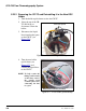
Figure 5-71 illustrates the liquid flow path through the eluent generator
components during initial filling of the EGC CO
3
Mixer with
carbonate/bicarbonate eluent.
Figure 5-71. Plumbing for Initial Filling of the EGC CO
3
Mixer with
Carbonate/Bicarbonate
EGC
IN
TO DEGAS
ELUENT OUT
WASTE,
GAS
SEPARATOR
TO INJ
VALVE IN - P/
ELUENT OUT
TO DEGAS
ELUENT IN
EGC
DEGAS
Connect to
Gas Separato
r
Assembly
Pre-plumbed
Pump Pulse
Damper
to
EGC CO
Mixer
3
TO CR-TC/EPM
REGEN IN
(orange)
TO PUMP/
DAMPER
TO CR-TC/EPM
ELUENT OUT
(yellow)
T
O
C
R
-
T
C
/
E
P
M
R
E
G
E
N
O
U
T
(
b
l
u
e
)
EPM
ELUENT IN
T
O
C
R
-
TC
/
E
P
M
E
L
U
E
N
T
I
N
(
r
e
d
)
EGC
OUT
(yellow)
(blue)
(red)
TO EGC CO3
MIXER IN
TO INJ VALVE
PORT P
TO EGC CO3
MIXER OUT
TO SRS/AES
REGEN OUT
Back-
Pressure
Coil*
*
14 MPa (2000 psi)
at 1.0 mL/min
From the EluGen
cartridge outlet port
To the EluGen
cartridge inlet port