Enhanced Model 2xx FOUNDATION Fieldbus™ Digital Output Software v3.
Read this Manual Before Installing This manual provides information on the Jupiter® magnetostrictive transmitter. It is important that all instructions are read carefully and followed in sequence. Detailed instructions are included in the Installation section of this manual. Conventions Used in this Manual Certain conventions are used in this manual to convey specific types of information. General technical material, support data, and safety information are presented in narrative form.
FOUNDATION Fieldbus™ Enhanced Jupiter® Model 2xx Magnetostrictive Level Transmitter Table of Contents 1.0 FOUNDATION fieldbus™ Overview ...................................4 1.1 Description ...............................................................4 1.2 Benefits .....................................................................5 1.3 Device Configuration................................................5 1.4 Intrinsic Safety ..........................................................6 2.
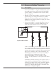
1.0 FOUNDATION fieldbus™ Overview 1.1 Description FOUNDATION fieldbus™ is a digital communications system that serially interconnects devices in the field. A Fieldbus system is similar to a Distributed Control System (DCS) with two exceptions: • Although a FOUNDATION fieldbus™ system can use the same physical wiring as an existing 4–20 mA device, Fieldbus devices are not connected point to point, but rather are multidropped and wired in parallel on a single pair of wires (referred to as a segment).
Details regarding cable specifications, grounding, termination, and other network information can be found in IEC 61158 or the wiring installation application guide AG-140 at www.fieldbus.org. 1.2 Benefits The benefits of FOUNDATION fieldbus™ can be found throughout all phases of an installation: 1. Design/Installation: Connecting multiple devices to a single pair of wires means less wire and fewer I/O equipment.
An important requirement of Fieldbus devices is the interoperability concept mentioned earlier. Device Description (DD) technology is used to achieve this interoperability. The DD provides extended descriptions for each object and provides pertinent information needed by the host system. DDs are similar to the drivers that your personal computer (PC) uses to operate peripheral devices connected to it.
2.0 Installation Caution: If equipment is used in a manner not specified by manufacturer, protection provided by equipment may be impaired This section provides detailed procedures for properly installing, wiring, configuring and, if needed, troubleshooting the Jupiter magnetostrictive level transmitter. In most cases the unit will be shipped from the factory attached to the Orion Instruments magnetic level indicator.
2.3 Before You Begin Caution: This instrument is intended for use in Installation Category II, Pollution Degree 2 locations. 2.3.1 Site Preparation Each Jupiter magnetostrictive transmitter is built to match the specifications required within the defined model option number. Wiring terminations will need to be made and the configuration will need to be accomplished.
2.3.3 Operational Considerations Exterior ambient temperature of the service should not exceed the design specifications of the electronics (-40° to +175° F (-40° to +80° C)). The operating temperature limits of the LCD are -5° to +160° F (-20° to +70° C). Temperatures below -5° F will cause the display to temporarily white out, and temperatures above +160° F will cause the display to go temporarily black. It will recover without damage when the operating temperature range returns.
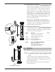
Upper Clamp Figure 2 2. Position the Jupiter transmitter on the side of the MLI where it will be attached. Mark the location and the exact area where the clamps will be attached to hold the Jupiter in place. 3. Attach the lower clamp and tighten so that it remains in place, but loose enough so that there is still room to place the guide tab from the Jupiter between the inside of the clamp and the outer diameter of the MLI chamber. See Figure 1. 4.
2.5 Wiring Caution: The Jupiter magnetostrictive transmitter operates at voltages of 9-32 VDC (nominal voltage is 24 VDC). Higher voltages will damage the transmitter. Wiring between the power supply and the Jupiter transmitter should be made using 18–22 AWG shielded twisted pair instrument cable. The transmitter enclosure consists of two compartments. The upper compartment is used to terminate the field wires (wiring termination compartment), and the lower compartment is the electronics compartment.
8. Power may be applied to the instrument when the installation is complete and has been checked by the instrument engineer or safety officer. 3.0 Function Blocks 3.1 Overview The Enhanced Jupiter Model 2xx is a level transmitter with four FOUNDATION fieldbus™ Function Blocks (one Resource Block, one Transducer Block, and two Analog Input blocks. The idea of Function Blocks, which a user can customize for a particular application, is a key concept of Fieldbus topology.
• The permitted modes are listed for each block. • The block must be in an automatic mode for normal operation. NOTE: The MODE_BLK target parameter must be OOS (out of service) to change configuration and calibration parameters in that function block (when in OOS, the normal algorithm is no longer executed and any outstanding alarms are cleared). All blocks must be in an operating mode for the device to operate.
DD_REV: contains the revision of the DD associated with the version of firmware in the Enhanced Jupiter transmitter. It is used by interface devices to correctly select the associated DD. RESTART: Default and Processor selections are available. Default will reset the Jupiter to the established block configuration. NOTE: As RESTART DEFAULT will set all configuration parameters to their default values.
FAULT_STATE, SET_FSTATE, CLR_FSTATE: these only apply to output function blocks. (The Model 2xx has no output function blocks). MAX_NOTIFY: the maximum number of alert reports that the transmitter can send without getting a confirmation. The user can set the number low, to control alert flooding, by adjusting the LIM_NOTIFY parameter value. LIM_NOTIFY: the maximum numbers of unconfirmed alert notify messages allowed. No alerts are reported if set to zero.
3.3 Transducer Block The TRANSDUCER block is a custom block containing parameters that support the enhanced level transmitter. It contains the Jupiter probe configuration, diagnostics, and calibration data, and outputs level with status information. The TRANSDUCER block parameters are grouped in a useful configuration. There are both read-only parameters and read-write parameters within the TRANSDUCER block. • The read-only parameters report the block status and operation modes.
3.3.3 Jupiter Configuration Parameters This set of parameters within the Transducer Block is important and required to configure every Jupiter transmitter. Sensor Mount MEASUREMENT_TYPE Select from LEVEL_ONLY or LEVEL&INTERFACE. 100% Set Point PROBE_LENGTH Enter the exact length of probe. The probe length is shown as the last 3 digits of the probe model number printed on the nameplate attached to the transmitter.
3.4.2 Firmware Version The last two parameters in the TRANSDUCER block show the firmware version of the transmitter. FIRMWARE_VERSION: displays the version of the firmware. COPROCESSOR_VERSION: displays the version of the coprocessor. 3.5 Analog Input Block The ANALOG INPUT (AI) block takes the transducer blocks input data, selected by channel number, and makes it available to other function blocks at its output: Channels 1. Level 2. Interface Level 3.5.
CHANNEL: The number of the logical hardware channel that is connected to this I/O block. This information defines the transducer to be used going to or from the physical world. L_TYPE: Determines if the values passed by the transducer block to the AI block may be used directly (Direct) or if the value is in different units and must be converted linearly (Indirect), or with square root (Ind Sqr Root), using the input range defined for the transducer and the associated output range.
HI_ALM: The status for high alarm and its associated time stamp. LO_ALM: The status for low alarm and its associated time stamp. LO_LO_ALM: The status for low low alarm and its associated time stamp. The TRANSDUCER and AI block’s MODE_BLK parameter must be set to AUTO to pass the PV Value through the AI to the network. Transducer scaling, called XD_SCALE, is applied to the PV from the CHANNEL to produce the FIELD_VAL in percent.
When the Model 2xx transmitter is initially powered on, the measurement engine does not have enough valid measurement cycles to make a decision about the output level. For the first sixteen measurement cycles after power is applied, the QUALITY is “Uncertain,” the SUB_STATUS is “Initial value,” and the LIMIT attribute is “Constant.” When the Model 2xx is operating correctly, the QUALITY is shown as “GOOD,” and the SUB_STATUS is “NonSpecific.
5.0 Reference Information 5.1 Troubleshooting The Jupiter transmitter is designed and manufactured for years of trouble free operation over a wide range of conditions. Common transmitter problems are discussed in terms of their symptoms and recommended corrective actions. 5.1.1 Troubleshooting Problem Solution Transmitter does not track level (External Mount) Remove transmitter from piping column and test with re-alignment magnet. Run magnet from bottom to top of probe.
5.1.
5.1.3 FF Segment Checklist • • • • There can be several reasons for a FOUNDATION fieldbus™ installation to be in a faulty condition. In order to assure that communication can be established, the following requirements must be met. Device supply voltage must be higher than 9 VDC with a maximum of 32 VDC. Total current draw of a given segment cannot exceed the rating shown on the power conditioner and/or barrier. Two 100 Ω, 1 µF terminators must be connected to the network—one at each end of the segment.
5.2.
5.2.
5.3 Specifications 5.3.1 Functional System Design Measurement Principle Magnetostrictive time-of-flight Input Measured Variable A return signal is generated from the precise location where the magnetic field of the MLI float intersects the magnetostrictive wire Zero and Span 6 inches to 400 inches (15 to 999 cm) User Interface Keypad 3-button menu-driven data entry and system security Indication 2-line × 8-character display Digital Communication FOUNDATION fieldbus™, H1 (31.
5.3 Specifications 5.3.3 Physical Enclosure finish: Baked on polymer powder coat Enclosure rating: NEMA 4X7/9, IP 66 Sensor length: 6 to 400 inches (15 to 999 cm) 11.5 (292) 11 (279) 12.5 (318) 8 (203) Inches (mm) 8.00 (203) 11.5 (292) Flanged or NPT Connection MAD E IN USA MAD E IN USA Top Mount Offset Top Mount Offset High Temperature Bend MAD E IN USA Direct Insertion 11.5 (292) 11 (279) 12.
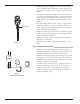
5.4 Parts 5.4.
5.5 References 1. FOUNDATION fieldbus™, A Pocket Guide Ian Verhappen, Augusto Pereira 2.
Jupiter Magnetostrictive Transmitter ® Configuration Data Sheet Copy blank page and store calibration data for future reference and troubleshooting.
ASSURED QUALITY & SERVICE COST LESS Service Policy Return Material Procedure Owners of Magnetrol/Orion Instruments controls may request the return of a or any part of an instrument for complete rebuilding or replacement. They will be rebuilt or replaced promptly. Instruments returned under our service policy must be returned by prepaid transportation.