Enhanced Model 705 Software v3.
Read this Manual Before Installing This manual provides information on the Eclipse® transmitter. It is important that all instructions are read carefully and followed in sequence. The QuickStart Installation instructions are a brief guide to the sequence of steps for experienced technicians to follow when installing the equipment. Detailed instructions are included in the Complete Installation section of this manual.
Eclipse® Guided Wave Radar Transmitter Table of Contents 1.0 QuickStart Installation 1.1 Getting Started..........................................................4 1.1.1 Equipment and Tools .....................................4 1.1.2 Configuration Information.............................5 1.2 QuickStart Mounting................................................5 1.2.1 Probe..............................................................5 1.2.2 Transmitter.....................................................
1.0 QuickStart Installation The QuickStart Installation procedures provide the key steps for mounting, wiring, and configuring the Eclipse® level transmitter. These procedures are intended for experienced installers of electronic level measurement instruments. See Complete Installation, Section 2.0, for detailed installation instructions. WARNING: The Model 7xD, 7xG, 7xR or 7xT overfill probes should be used for Safety Shutdown/Overfill applications.
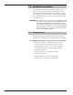
1.1.2 Configuration Information Some key information is needed to configure the ECLIPSE transmitter. Complete the following operating parameters table before beginning configuration. Display Probe Model Probe Mount _____________ What units of measurement will be used? (inches, centimeters, feet or meters) Loop Control Set 4.
1.2.2 Transmitter Tighten the hex nut of the probe process connection or flange bolts. NOTE: Leave the plastic protective cap in place until ready to install the transmitter. Do not use sealing compound or TFE tape on probe connection to transmitter as this connection is sealed by a Viton® O-ring. Remove the protective plastic cap from the top of the probe and store for future use. Make sure the top probe connector (female socket) is clean and dry.
QuickStart Configuration Up 4. 6. 7. 5. Down 2. 3. Enter 1. The ECLIPSE transmitter comes configured with default values from the factory but can be reconfigured in the shop (disregard any fault messages due to unattached probe). The minimum configuration instructions required in the field follow. Use the information from the operating parameters table in Section 1.1.2 before beginning configuration. Power up the transmitter.
2.0 Complete Installation This section provides detailed procedures for properly installing and configuring the ECLIPSE Guided Wave Radar Level Transmitter. 2.1 Unpacking Unpack the instrument carefully. Make sure all components have been removed from the packing material. Check all the contents against the packing slip and report any discrepancies to the factory. Before proceeding with the installation, do the following: • Inspect all components for damage.
2.3 Before You Begin 2.3.1 Site Preparation Each ECLIPSE transmitter is built to match the specific physical specifications of the required installation. Make sure the probe connection is correct for the threaded or flanged mounting on the vessel or tank where the transmitter will be placed. See Mounting, Section 2.4. Make sure that the wiring between the power supply and ECLIPSE transmitter are complete and correct for the type of installation. See Specifications, Section 3.6.
WARNING! The Model 7xD, 7xR or 7xT overfill probes should be used for Safety Shutdown/Overfill applications. All other Guided Wave Radar probes should be installed so the maximum overfill level is a minimum of 6" (150 mm) below the process connection. This may include utilizing a nozzle or spool piece to raise the probe. Consult factory to ensure proper installation. WARNING! Do not disassemble probe when in service and under pressure. 2.4.
2.4.2 Installing a Twin Rod Probe (Models 7xB, 7x5, and 7x7) Before installing, make sure the: • Model and serial numbers on the nameplates of the ECLIPSE probe and transmitter are identical. • Probe has adequate headroom for installation and has unobstructed entry to the bottom of the vessel. • Process temperature, pressure, dielectric, viscosity, and media buildup are within the probe specifications for the installation. See Specifications, Section 3.6.
2.4.2.2 To install a Model 7x7 standard flexible twin rod probe: Make sure the process connection is at least 2" NPT or a flanged mounting. Make sure that there is at least 1" (25 mm) spacing between the active probe rod and any part of the tank (walls, stillwell, pipes, support beams, mixer blades, etc.). Minimum stillwell diameter for Twin Rod probe is 3". Carefully place the probe into the vessel. Align the gasket on flanged installations.
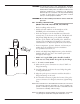
B A 2. Ratio of Diameter: Length (A:B) is 1:1 or greater; any ratio <1:1 (e.g., a 2"× 6" nozzle = 1:3) may require a Blocking Distance and/or DIELECTRIC adjustment (see Section 2.6.5.2 Measurement Type: Level and Volume). 3. No pipe reducers (restrictions) are used. • Probe is kept away from conductive objects to ensure proper performance. See Probe Clearance Table below. A lower gain (increase in DIELECTRIC setting) may be necessary to ignore certain objects (see Section 2.6.5.
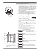
➀ ➁ Align the probe process connection with the threaded or flanged mounting on the vessel. For threaded connections, tighten the hex nut of the probe process connection. For flanged connections, tighten flange bolts. ➃ ➂ Probe can be shortened in field: a. Raise TFE weight (1) exposing securing device (2). b. Loosen both #10–32 set screws (3) using 3⁄32" (2.5 mm) hex wrench and remove securing device. c. Cut and remove needed cable (4) length. d. Reattach securing device and tighten screws. e.
Make sure that there is at least 1" (25 mm) spacing between the active probe rod and any part of the tank (walls, stillwell, pipes, support beams, mixer blades, etc.). Minimum stillwell diameter for Twin Rod probe is 3". Carefully place the probe into the vessel. Align the gasket on flanged installations. Align the probe process connection with the threaded or flanged mounting on the vessel. For threaded connections, tighten the hex nut of the probe process connection.
2.4.5 Installing the Transmitter The transmitter can be ordered for installation as an Integral or Remote configuration. 2.4.5.1 Integral Mount Remove the protective plastic cap from the top of the probe. Store the cap in a safe place in case the transmitter has to be removed later. Place the transmitter on the probe. Be careful not to bend probe. Do not allow the gold, high frequency (male) connector to get dirty.
2.5 Wiring Caution: All HART versions of the ECLIPSE Model 705 transmitter operate at voltages of 11–36 VDC. Higher voltage will damage the transmitter. Wiring between the power supply and the ECLIPSE transmitter should be made using 18–22 AWG shielded twisted pair instrument cable. Within the transmitter enclosure, connections are made to the terminal strip and the ground connections.
2.5.2 Intrinsically Safe An intrinsically safe (IS) installation potentially has flammable media present. An approved IS barrier must be installed in the non-hazardous (safe) area. See Agency Drawing – Intrinsically Safe Installation, Section 3.4.2. To install Intrinsically Safe wiring: 1. Make sure the IS barrier is properly installed in the safe area (refer to local plant or facility procedures). Complete the wiring from the barrier to the ECLIPSE transmitter. 2.
2.6 Configuring the Transmitter The ECLIPSE transmitter comes configured from the factory but can be reconfigured easily in the shop (disregard error message due to unattached probe). Bench configuration provides a convenient and efficient way to set up the transmitter before going to the tank site to complete the installation. Before configuring the transmitter, collect the operating parameters information (refer to Section 1.1.2).
2.6.3 Transmitter Display and Keypad The ECLIPSE transmitter has an optional liquid crystal display (LCD) capable of showing two lines of 8 characters each. Transmitter measurements and configuration menu screens are shown on the LCD. The transmitter default display is the measurement screen. It cycles every 5 seconds to display STATUS, LEVEL, %OUTPUT, and LOOP information (LEVEL, %OUTPUT, and STATUS for Fieldbus version).
2.6.5 Model 705 Menu: Step-By-Step Procedure The following tables provide a complete explanation of the software menus displayed by the ECLIPSE transmitter. Use these tables as a step-by-step guide to configure the transmitter based on a desired measurement type of: • Level Only, Section 2.6.5.1 • Level and Volume, Section 2.6.5.2 • Interface Level, Section 2.6.5.3 • Interface Level and Volume, Section 2.6.5.4 The tables are separated to display the parameters based on the measurement type.
2.6.5.1 Measurement Type: Level Only (Loop Control = Level) Display Action Comment Senstvty xxx Enter value upward or downward to sense liquid surface Allows fine gain adjustment for single rod probes (this parameter is password protected for coaxial and twin rod probes). 13 LoopCtrl (select) Select variable to control loop current Select Level 14 Set 4mA xxx.x 1u Enter the PV value for the 4 mA point A small transition zone (0–6") may exist at the top/bottom of the probe.
2.6.5.
2.6.5.2 Measurement Type: Level and Volume (Loop Control = Volume) Display Action Comment *Status* *Volume* *% Out * * Loop * Transmitter Display 1 LoopCtrl = Volume Transmitter default display showing: Status, Volume, % Output and Loop values cycles every 5 seconds 2 Volume xxx vu Transmitter Display Transmitter displays Volume in selected units 3 % Output xx.x% Transmitter Display Transmitter displays % Output measurement derived from 20 mA span 4 Loop xx.
2.6.5.2 Measurement Type: Level and Volume (Loop Control = Volume) Display Action Comment 22 SZ Fault (select) Select loop current behavior Safety Zone is a user-defined area just below the Blocking when level is sensed in safety Distance. Enable Fault if necessary to ensure safe, reliable highzone level readings in critical applications. Choices are None, 3.6 mA, 22 mA, Latch 3.6 or Latch 22. If Latch 3.
2.6.5.
2.6.5.3 Measurement Type: Interface Level (Loop Control = Interface Level) Display Action Comment *Status* *IfcLvl* *% Out * * Loop * Transmitter Display 1 LoopCtrl = IfcLevel Transmitter default display showing Status, IfcLevel, % Output, and Loop values cycles every 5 seconds 2 IfcLvl xxxx vu Transmitter Display Transmitter displays interface level in selected units 3 % Output xx.x% Transmitter Display Transmitter displays % Output measurement derived from 20 mA span 4 Loop xx.
2.6.5.3 Measurement Type: Interface Level (Loop Control = Interface Level) Display 28 21 SZ Fault (select) 22 SZ Height xx.x lu 23 SZ Alarm Reset 24 Action Comment Select loop current behavior Safety Zone is a user-defined area just below the Blocking when level is sensed in safety Distance. Enable Fault if necessary to ensure safe, reliable highzone level readings in critical applications. Choices are None, 3.6 mA, 22 mA, Latch 3.6 or Latch 22. If Latch 3.
2.6.5.
2.6.5.4 Measurement Type: Interface and Volume Display Action Comment *Status* *IfcLvl* *% Out * * Loop * Transmitter Display 1 LoopCtrl = IfcLevel and Volume Transmitter default display showing Status, Interface Level, Volume, % Output, and Loop values cycles every 5 seconds 2 IfcLevel xxx.x lu Transmitter Display LoopCtrl = IfcLevel 3 Ifc Vol xxxx vu Transmitter Display LoopCtrl = Ifc Vol 4 % Output xx.
2.6.5.4 Measurement Type: Interface and Volume Display Action Comment BlockDis xx.x lu Enter distance below Allows user to ignore level measurements near the top of the reference point where level is probe not sensed 25 SZ Fault (select) Select lop current behavior Safety Zone is a user-defined area just below the Blocking when level is sensed in safety Distance. Enable Fault if necessary to ensure safe, reliable highzone level readings in critical applications. Choices are None, 3.
2.6.5.
2.6.6 Offset Description LvlUnits in PrbModel 7xA-x PrbMount NPT 20 mA Probe Ln 72 in Lvl Ofst 0.0 in 60" Dielctrc 10-100 4 mA Set 4mA 24.0 in 24" Set 20mA 60.0 in 10" Example 1 LvlUnits in PrbModel 7xA-x PrbMount NPT Probe Ln 72 in 20 mA Lvl Ofst 10 in The parameter referred to as Lvl Ofst in the ECLIPSE menu is the desired level reading when liquid surface is at the end of the probe. The ECLIPSE transmitter is shipped from the factory with Lvl Ofst set to 0.
2.6.7 Strapping Table Description The Model 705 is available with a 20-point custom strapping table. Up to 20 pairs of Level—Volume points can be entered to linearize the 4-20 mA output for odd-shaped vessels. There are two ways to enter data into the strapping table. 1. 2. 3. 4. 5. 6. Procedure 1 (this method is the most common): Ensure that “Level and Volume” is selected as the Measurement Type (parameter 8 in table 2.6.5.2). Ensure that the correct Level Units and Volume Units are chosen.
2.7 Configuration Using HART A HART (Highway Addressable Remote Transducer) remote unit, such as a HART communicator, can be used to provide a communication link to the ECLIPSE transmitter. When connected to the control loop, the same system measurement readings shown on the transmitter are shown on the communicator. The communicator can also be used to configure the transmitter. The HART communicator may need to be updated to include the ECLIPSE software (Device Descriptions).
2.7.3 HART Menu – Model 705 3.
2.7.4 HART Revision Table Model 705 HART Version HCF Release Date Compatible with 705 Software Dev V1 DD V1 July 1998 Version 1.2B and earlier Dev V1 DD V2 November 1998 Version 1.2C through 1.3D Dev V3 DD V1 April 1999 Version 1.4A through 1.4C Dev V4 DD V1 October 1999 Version 1.5 and later Model 705 2.x HART Version HCF Release Date Compatible with 705 Software Dev V1 DD V1 June 2000 Version 2.0A through 2.2C Dev V2 DD V1 September 2001 Version 2.3A through 2.
Details regarding cable specifications, grounding, termination, and other network information can be found in IEC 61158 or at www.fieldbus.org. 6234 feet (1900 meters) maximum PC Power Conditioner Terminator Terminator Power Supply Control Room Typical Fieldbus Installation 2.8.2 Benefits The benefits of Fieldbus can be found throughout all phases of an installation: 1. Design/Installation: Connecting multiple devices to a single pair of wires means less wire and fewer I/O equipment.
2.8.3 Device Configuration Device Descriptions The function of a Fieldbus device is determined by the arrangement of a system of blocks defined by the Fieldbus Foundation. The types of blocks used in a typical User Application are described as follows: Resource Block describes the characteristics of the Fieldbus device such as the device name, manufacturer, and serial number. Transducer Blocks contain information such as calibration date and sensor type.
FISCO certifying agencies have limited the maximum segment length to 1000 meters because the FISCO model does not rely on standardized ignition curves. The ECLIPSE Model 705 is available with an entity IS, FISCO IS, and explosion proof approvals. 3.
3.2.2 Interface Detection The ECLIPSE Model 705, when used with the Model 7xT coaxial probe, is a transmitter capable of measuring both an upper level and an interface level. It is required that the upper liquid have a dielectric constant between 1.4 and 5 and the two liquids have a difference in dielectric constants greater than 10.
3.2.3 Time Domain Reflectometry (TDR) TDR uses pulses of electromagnetic (EM) energy to measure distances or levels. When a pulse reaches a dielectric discontinuity (created by media surface), part of the energy is reflected. The greater the dielectric difference, the greater the amplitude (strength) of the reflection. Although TDR is new to the industrial level measurement industry, it has been used in the telephone, computer, and power transmission industries for years.
3.3 Troubleshooting The ECLIPSE transmitter is designed and engineered for trouble-free operation over a wide range of operating conditions. Common transmitter problems are discussed in terms of their symptoms and recommended corrective actions. Information on how to handle material buildup on the probe is also provided in this section. WARNING! Explosion hazard. Do not connect or disconnect equipment unless power has been switched off or the area is known to be non-hazardous. 3.3.
3.3.2 Status Messages Display Message Action Comment OK None Normal operating mode Initial None Program is Initializing, level reading held at 4 mA set point. This is a transient condition. DryProbe None Normal message for a dry probe. End of probe signal is being detected.
3.3.2 Status Messages Display Message Action Comment Present temperature in electronics compartment is below -40° C 1) Transmitter may need to be moved to ensure ambient temperature is within specification HiVolAlm Level more than 5% above highest point in strapping table Verify strapping table is entered correctly. None. Signal amplitude is lower than desired.
3.3.3 Troubleshooting Applications There are numerous causes for application problems. Media buildup on the probe and stratification are covered here. Media buildup on the probe is not a problem in most cases —ECLIPSE circuitry typically works very effectively. Media buildup should be viewed as two types—Film Coating and Bridging. A twin rod probe can be utilized when minor film coating is a possibility. For more extreme buildup, utilize the Model 7xF or 7x1 Single Rod Probes. Film Coating Bridging 3.3.
3.3.3.
3.4 Agency Approvals AGENCY FM CSA IEC ATEX 0344 MODEL APPROVED APPROVAL CATEGORY APPROVAL CLASSES 705-5XXX-1XX 705-5XXX-2XX Intrinsically Safe 705-5XXX-3XX 705-5XXX-4XX Explosion Proof (with Intrinsically Safe probe) 705-5XXX-XXX 705-5XXX-XXX Non-Incendive Suitable for: 705-5XXX-1XX 705-5XXX-2XX Intrinsically Safe 705-5XXX-3XX 705-5XXX-4XX Explosion Proof (with Intrinsically Safe probe) 705-5XXX-XXX 705-5XXX-XXX Non-Incendive Suitable for: Class I, Div.
3.4.
3.4.
3.5 Parts 3.5.
3.6 Specifications 3.6.1 Functional System Design Measurement Principle Guided time-of-flight via time domain reflectometry Input Measured Variable Level, determined by the time-of-flight of a guided radar pulse from transmitter to product surface and back Zero and Span 6 inches to 75 feet (15 to 2286 cm) Output Type Analog 4 to 20 mA with HART digital signal (HART 6) Range Analog 3.8 to 20.5 mA useable Digital 0 to 999" (0 to 999 cm) Analog 0.01 mA 1200 Digital 0.
Environment Operating Temperature -40 to +175° F (-40 to +80° C) Display Function Operating Temperature -5 to +160° F (-20 to +70° C) Storage Temperature -50 to +175° F (-46 to +80° C) Humidity 0-99%, non-condensing Electromagnetic Compatibility Meets CE Requirements: EN 61326 Note: Twin Rod and Single Rod probes must be used in metallic vessel or stillwell to maintain CE requirement. Mounting Affects: Twin Rod Active rod must be mounted at least 1" (25 mm) from any surface or obstruction.
3.6.3 Performance - Model 705 Interface Reference Conditions Reflection from liquid of selected dielectric at +70° F (+20° C) with 72" probe Linearity <0.5 inch Measured Error Upper layer ±1 inch Interface layer ±1 inch (clean distinct interface required) Upper Layer Dielectric 1.4–5.0 Interface Layer Dielectric >15 Resolution ±0.1 inch Repeatability <0.5 inch Hysteresis <0.5 inch Response Time <1 second Warm-up Time <5 seconds Operating Temp.
3.6.5 Probe Specifications Dual-element Probes Coaxial (7xA, 7xR, 7xT) Model Materials Diameter Process Connection Rigid Twin Rod (7xB) Flexible Twin Rod (7x5, 7x7) HTHP Coaxial (7xD) HP Coaxial (7xP) Steam (7xS) 316/316L SS, 316/316L SS, 316/316L SS, Inconel® X750, Inconel® X750, Peek™, Borosilicate seal, Borosilicate seal, Aegis PF 128 O-ring TFE or Peek™ spacers TFE spacers .3125" (8mm) dia. rod Two .5" (13 mm) dia. Two .25" (6 mm) dia. .3125" (8 mm) diameter rod Rods, .375" .875" (10mm) dia.
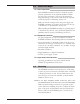
Temperature/Pressure Charts 1200 200 1000 900 800 700 600 500 400 300 200 100 0 -40 180 Ambient Temperature (°F) Process Pressure (psig) 1100 0 100 200 300 160 140 120 100 80 60 40 20 400 0 Process Temperature (°F) (max.
3.6.6 Physical – Coaxial Probes inches (mm) COAXIAL PROBES D Dimension Standard Enlarged .875 (22) 1.75 (44) .875 (22) 1.75 (44) .875 (22) 1.75 (44) .875 (22) 1.75 (44) .875 (22) — Probe 7xA 7xD 7xP 7xR, 7xT 7xS 3.28 (83) H Dimension NPT Flanged 2.32 (59) 2.91 (74) 8.55 (217) 10.91 (277) 4.18 (106) 6.54 (166) 5.89 (150) 6.57 (167) 7.10 (180) 9.52 (242) 4.12 (105) 3.28 (83) 3.28 (83) 4.12 (105) 4.00 (102) 4.00 (102) 10.08 (256) 10.08 (256) 4.12 (105) 3.28 (83) Elect. Conn. Qty. 2 102 (4.00) 10.
3.6.6 Physical – Twin Rod Probes inches (mm) 0.88 (22) Ø .50 (13) Rods 0.38 (10) Mounting Flange Process Conn. Twin Rod Probe End View 5.08 (129) 4.96 (126) Probe Insertion Length Probe Insertion Length Eclipse® with 7xB Twin Rod Probe – NPT Connection Mounting Flange NPT Process Connection Mounting Flange NPT Process Connection 2.80 (71) 3.13 (80) 1.75 (44) 3.00 (76) 3.00 (76) 3.
3.6.6 Physical – Single Rod Probes inches (mm) Process Conn. 7xF: 2.36 (60) 7xJ: 4.96 (126) 7xF: 2.24 (57) 7xJ: 4.84 (123) Ø 0.50" (12) Rod Probe Insertion Length Probe Insertion Length 2.36 (60) 2.36 (60) Ø 0.50" (12) Rod Ø 0.50" (12) Rod Ø 0.50" (12) Rod Sanitary Conn. Probe Insertion Length Probe Insertion Length 0.625" (16) O.D.
3.7 Model Numbers 3.7.1 Transmitter BASIC MODEL NUMBER 705 ECLIPSE Guided Wave Radar Level Transmitter POWER 5 24 VDC, Two-wire SIGNAL OUTPUT AND ELECTRONICS 10 1A 20 30 4–20 mA with HART – SIL 1 standard electronics (SFF of 85.
3.7.2 Probe BASIC MODEL NUMBER 7E 7M ECLIPSE GWR probe, English unit of measure ECLIPSE GWR probe, Metric unit of measure CONFIGURATION/STYLE D R L M N S T B 7 5 F G J 1 2 Coaxial Coaxial Coaxial Coaxial Coaxial Coaxial Coaxial Twin Rod Twin Rod Twin Rod Single Rod Caged Single Rod Single Rod Single Rod High Temp./High Pressure Overfill Probe 3 High Temp./High Pressure w/Flushing Conn. ⁄4" process connection Overfill Probe w/Flushing Conn. or larger Interface Probe w/Flushing Conn.
3.7.
PROPRIETARY AND SPECIALTY FLANGE CONNECTIONS TT TU UT UU 31⁄2" 31⁄2" 31⁄2" 31⁄2" 600# 600# 600# 600# Fisher® - Proprietary Carbon Steel (249B) Torque Tube Flange Fisher - Proprietary 316 Stainless Steel (249C) Torque Tube Flange Masoneilan® - Proprietary Carbon Steel Torque Tube Flange Masoneilan - Proprietary 316 Stainless Steel Torque Tube Flange DIN FLANGE CONNECTIONS BA BB BC BF CA CB CC CF CG CH CJ DA DB DD DE DF DG DH DJ DN DN DN DN DN DN DN DN DN DN DN DN DN DN DN DN DN DN DN 25, 25, 25, 25, 40
Glossary Accuracy The maximum positive and negative % deviation over the total span. Fault A defect or failure in a circuit. The current (mA) value unit defaults to 3.6, 22, or Hold when a diagnostic condition occurs. ANSI American National Standards Institute. Feedthrough A small connecting cavity between the main housing compartments, carrying the cable that supplies the operating energy to the measurement circuitry and returns the output value proportional to level.
Intrinsic Safety A design or installation approach that limits the amount of energy that enters a hazardous area to eliminate the potential of creating an ignition source. Level The present reading of the height of material in a vessel. Linearity The worst case error calculated as a deviation from a perfect straight line drawn between two calibration points. Line-Powered See Four Wire. Loop The present reading of the 4-20 mA current output. Loop-Powered See Two Wire.
705 Eclipse® Guided Wave Radar Transmitter Configuration Data Sheet Copy blank page and store calibration data for future reference and troubleshooting. Item Vessel Name Vessel # Process Medium Tag # Electronics Serial # Probe Serial # Level Volume (optional) Interface (optional) Interface Volume (opt.) Probe Model Probe Mount Measurement Type Level Units Probe Length Level Offset Volume Units (opt.) Strapping Table (opt.
705 Eclipse® Guided Wave Radar Transmitter Configuration Data Sheet Copy blank page and store calibration data for future reference and troubleshooting.
ASSURED QUALITY & SERVICE COST LESS Service Policy Return Material Procedure Owners of MAGNETROL controls may request the return of a control or any part of a control for complete rebuilding or replacement. They will be rebuilt or replaced promptly. Controls returned under our service policy must be returned by prepaid transportation.