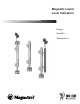
Magnetic Liquid Level Indicators Installation and Operating Manual Gauges Switches Transmitters A Magnetrol Company
Read this Manual Before Installing This manual provides information on Magnetic Liquid Level Indicators. It is important that all instructions are read carefully and followed in sequence. Notice of Trademark, Copyright, and Limitations Magnetrol & Magnetrol logotype, Orion Instruments, Aurora, Eclipse, and Jupiter are trademarks of Magnetrol International. Conventions Used in this Manual Certain conventions are used in this manual to convey specific types of information.
Magnetic Liquid Level Indicators Table of Contents 1.0 Installation 1.1 Unpacking.............................................................4 1.2 Pre-installation Checklist .......................................4 1.3 Equipment and Tools ............................................4 1.4 Side Mount Installation.........................................5 1.5 Top Mount Installation .........................................6 1.6 Top/Bottom Connection Installation.....................6 1.7 Start-up ............
1.0 Installation Caution: If equipment is used in a manner not specified by manufacturer, protection provided by equipment may be impaired. 1.1 Unpacking Unpack the instrument carefully. Inspect all units for damage. Report any concealed damage to carrier within 24 hours. Check the contents of the packing slip and purchase order. Check and record the serial number for future reference when ordering parts. Caution: Do not discard the shipping container until all parts are checked. 1.
1.4 Side Mount Installation Caution: This instrument is intended for use in Installation Category II, Pollution Degree 2 locations. NOTE: Top of gauge nameplates are available as an option. The MLI nameplate can be used as bottom reference of the external cage. Install the cage to the vessel with nameplate at bottom. Isolation valves are recommended for installation between vessel and external cage. Check to ensure the external cage is vertical.
1.5 Top Mount Installation Caution: This instrument is intended for use in Installation Category II, Pollution Degree 2 locations. The top mount gauge can be installed as one complete unit or disassembled to allow access from inside the tank. Correct vertical installation is required to assure proper float movement. To disassemble you need only to unscrew the threaded cap at the bottom mounting flange or connection. Caution: Proper precautions should be taken to prevent the bending of the guide rod. 1.
1.8 Special Accessory Installation 1.8.1 Insulation or Blanket Installation Factory recommended high temperature insulation specifications: Temperature 0° to +250° F (-18° to +121° C) Thickness ⁄2" Liner Jacket 1 +251° to +500° F (+122° to +260° C) 1" +501° to +1000° F (+261° to +538° C) 2" Weather resistant silicone cloth Weather resistant silicone cloth Weather resistant aluminized silicone cloth • Thickness is 1⁄2" when the MLI has switches or a transmitter. • Insulation used is 8 lb.
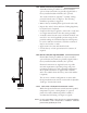
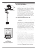
1.8.2 Steam Heat Tracing Installation Steam Heat Tracing is available as a factory installed option. Steam traced units are generally supplied with a factory installed insulation blanket (also optional). Two steam connections (typically 3⁄8" × 0.035" tubing) protrude from the unit. See Figure 2. The following installation procedure is suggested: Figure 2 • Remove factory installed plastic caps from the tube ends. • Inspect tube ends for dents and burrs. Tubing length may be adjusted (cut), if required.
1. Locate specific power specification and wiring diagram supplied with unit. 2. Provide appropriate conduit and wiring to the unit. 3. Apply sufficient operating power. 4. Verify that unit will generate sufficient heat and maintain proper temperature. NOTE: Wiring diagrams are supplied with units manufactured with this option. 1.8.3.
1.9 inches (mm) 3.0 (76) REF. Switch Installation 1.9.1 OES Cam Operated Switch 5.5 (139) 8.375 (212) REF. REF. .5 (12) REF. (2) 3/4" NPT conduit connections The Model OES snap switch is utilized to expand the control capabilities of Orion’s extensive line of magnetic level indicators. This cam-operated double pole double throw mechanism is clamp-mounted to the outside of the MLI. This mounting style allows easy addition or repositioning of switches without disruption of the process.
1.9.1.3 Wiring The lower conduit opening is protected with a plastic shipping plug. The upper opening is sealed with a steel plug. If it is preferable to wire through the upper conduit entry, the steel plug may be moved to the lower opening. NOTE: For supply connections, use wire with a minimum rating of +167˚ F (+75˚ C) as required by the process conditions. Use a minimum of 14 AWG wire for power and ground field wires. NOTE: Housing must be grounded via protective ground screw in base of housing.
1.9.2.1 Mounting to an Atlas or Gemini MLI Caution: If equipment is used in a manner not specified by the manufacturer, protection provided by the equipment may be impaired. inches (mm) 8-32 Ground Screw 3.00 (76.2) 0.84 (21.3) 3.00 (76.2) 1/2" MNPT 1.00 (25.4) With mounting clamps loosened, position ORS reed switch on the MLI body so that the centerline of the stainless steel tube which houses the switch is at the desired switch point level.
1.10 Analog Transmitter Installation inches (mm) 1.10.1 OCT Reed Transmitter 3.8 (140) REF. Label bracket 0.4 (10) REF. 3.5 (90) REF. 4.5 (115) REF. 3/4" NPT conduit connection The OCT analog transmitter mounts directly to the side of the Atlas or Gemini chamber, providing a continuous 4–20 mA output signal proportional to liquid level. Using simple and reliable reed switches surface mounted to a printed circuit board, the unit provides level accuracy of ±0.50" (13 mm).
1.12 Internal Eclipse Transmitter Installation The Eclipse Guided Wave Radar Transmitter can be mounted in either the Gemini or the Aurora MLIs. The Aurora is designed to support operation of the Eclipse in the same chamber as the float. Due to this, the coaxial type probe must be used. With the dual chamber Gemini design, either the twin rod, coaxial, or single rod types may be used.
Local indication, 4–20 mA output, HART and Fieldbus protocols are available. Float damage will not result in loss of the 4–20 mA signal Aurora: The Eclipse Guided Wave Radar probe is mounted directly inside of the Gemini chamber. a minimum 3" chamber is utilized to accommodate the Eclipse probe and allow unobstructed float travel. Patent pending. Gemini: The dual chamber approach also accomplishes total redundancy but increases the ease of gauge or transmitter isolation.
2.3 Troubleshooting 2.3.1 Side Mount Problem Flags do not rotate with level change. Flags rotate at different height than actual level. Float inside the level gauge is moving slow or not at all. Solution Test flags with a magnet from bottom to top (magnet not included). If flags test okay, check for float obstruction. (See Section 2.5, Maintenance on page 16) Float selected for different specific gravity. Replace float with a float with correct specific gravity rating.
2.3.2 Top Mount Problem The float assembly or visual indicator is moving slowly or not at all. Solution Make sure the vessel opening or flange connection that the to mount flange connects to is level. The top mount guide rod assembly may be bent. Visual inspection is required. The process fluid in the vessel may be too viscous, Heating the vessel to make the process fluid more liquid may be required. The specific gravity of the process fluid and the float may need to be reverified.
2.6 Specifications 2.6.
2.6.2 Model OES Switch • • • • • Electric snap action switch 10 amp DPDT ±0.75" (19 mm) float travel -58° to +392° F (-50° to +200° C) Cast aluminum enclosure, (2) 1⁄2" NPT conduit entries See bulletin OES for further information 2.6.3 Model ORS Switch • Electric reed switch, hermetically sealed • 1 amp SPDT • • • • Stainless steel enclosure with mounting tabs ±0.
ASSURED QUALITY & SERVICE COST LESS Service Policy Return Material Procedure Owners of Magnetrol/Orion Instruments controls may request the return of a or any part of an instrument for complete rebuilding or replacement. They will be rebuilt or replaced promptly. Instruments returned under our service policy must be returned by prepaid transportation.