PowerScan® Handheld Laser Scanner Programming Guide
PSC Inc 959 Terry Street Eugene, Oregon 97402 Telephone: (541) 683-5700 Fax: (541) 345-7140 An Unpublished Work - All rights reserved. No part of the contents of this documentation or the procedures described therein may be reproduced or transmitted in any form or by any means without prior written permission of PSC Inc. or its wholly owned subsidiaries ("PSC").
Table of Contents Introduction ..................................................................................................................................1 Understanding the Basics............................................................................................................1 Integrating the Scanner With Your Host System .........................................................................2 Changing Interfaces ..........................................................................
Universal Wedge Terminal Selection ................................................................... 44 Terminal/Keyboard Settings ................................................................................. 44 Universal Wedge Number Pad ............................................................................. 45 IBM Interface ............................................................................................................... 46 Transmit Labels in Code 39 Format .......................
Configuring the Standard 2 of 5 Options .............................................................117 IATA ...........................................................................................................................123 MSI/Plessey Options .................................................................................................124 Configuring the MSI /Plessey Options ................................................................126 General Features.................................
Blank Page iv PowerScan® Scanner
Introduction The programming bar code labels contained in this manual will allow you to customize and configure features and settings for your PSC® PowerScan™ scanner. To ensure full compatibility and proper function, use only the programming bar codes in this manual and other productspecific publications to program scanner features. This manual has been developed to make it quick and easy for users of all levels to find the information needed to understand and configure scanner features.
Integrating the Scanner With Your Host System Your scanner MUST be equipped with the correct hardware (interface board, cable, etc.) to properly communicate with your host system. Contact your PSC dealer for information if you have questions about your scanner’s hardware compatibility. You may also want to contact the dealer or your system administrator if you have no record of how your scanner was pre-programmed at the factory.
To determine if your desired new interface is available on your scanner, check the following section titled Software on page 4. The section lists host interface types supported by each interface board available at the time of this writing. If you are still unsure of your scanner’s available interface connectivity, consult your PSC dealer.
Software Verify that your scanner supports the desired interface1. The list below indicates the interface groupings the scanner supports. Contact your nearest PSC service depot if you don’t know your scanner’s group, or need assistance to change the scanner to another interface group.
After familiarizing yourself with the basic scanner programming procedures in this section, turn to the appropriate interface programming section (RS-232, Wand Emulation, etc.) of this manual to set other interface features, completing the scanner’s conversion to a new interface type. Upon changing a scanner’s interface setting, scan a bar code to verify that the scanner communicates correctly with the new host system. Some sample bar codes are provided in Appendix B: Sample Bar Codes on page 145.
Programming Overview The scanner’s programmable feature settings can be modified to accommodate your system’s unique requirements. These settings can be communicated to the scanner in one of two ways: 1. Commands can be sent directly from the host. A limited set of host commands are available. Refer to Appendix A: Additional Information on page 143 for more details. 2. The easiest, most comprehensive way to program the scanner is to use the Configurator Express™ On-Screen Programmining Kit.
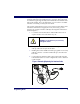
Programming Session A typical programming session is conducted as follows: 1. Scan the SET bar code at the beginning of each set of programming bar codes to place the scanner in Programming Mode. The scanner will emit three beeps, indicating it has read the bar code and the green LED will flash on and off slowly while the scanner remains in Programming Mode. Normal scanning functions are disabled. 2. Scan the programming label(s) that is (are) specially encoded to make the desired changes.
NOTE 3. It is recommended that programming sessions be limited to one feature at a time. Should you make a mistake in the programming sequence, it can be difficult to discover where an error has been made if several features are programmed at once. Additionally, it can be confusing to determine which features may or may not have been successfully set following such a session. Scan the END label at the bottom of the page to save any new settings and exit Programming Mode.
Programming To modify a scanner feature (item), the programming bar codes conSequence tained in this manual must be scanned in a given sequence depending upon the feature being programmed (as shown in Table 1). There are three possible programming sequences: A. Programming sample A (the most commonly used format) demonstrates how three bar codes are scanned in sequence to do the following: 1. Place the scanner in Programming Mode (SET bar code). 2. Scan the Item Tag1 that will enable the new feature. 3.
Table 1. Programming Sequence SET A ITEM TAG ITEM VALUE END/RESET 1 2 3 SET ENABLE NEW FEATURE END 1 2 345 6 0 B SET C 10 ENABLE NEW FEATURE USING THE FOLLOWING SETTINGS...
LED and Beeper Indicators The scanner provides a set of indicators that verify/announce the various scanner functions. LED Indicators The Amber “Laser ON” LED (located on top rear of scanner) - lights whenever laser power is on. The Green “Good Read” LED (also located on top rear of scanner) - Flashes1 once to indicate when a “good read” has occurred. - Flashes1 slowly on and off to indicate the scanner is in Programming Mode. The Beeper While in Scanning mode... - Sounds1 four times at power-up.
If You Make a Mistake... If, during a programming session, you find that you are unsure of the scanner’s settings or wish to reset the scanner’s configuration, use the Return to Factory Settings label below to return the scanner’s configuration to the factory settings. Scanning this label will also reset any changes made during previous programming sessions. Return to Factory Settings Scan this label to return the scanner to the default settings configured at the factory.
Where To Go From Here Programming is easy and straightforward if you follow these steps: NOTE If you are changing some interface types (for example; if you are moving the scanner from a Universal Keyboard Wedge to an RS-232 host) you must first change the hardware. Replace the scanner’s interface board (if required) and connect the scanner using the new interface cable BEFORE performing any programming changes. 1.
Interface Selection This section contains programming bar code labels to select the following interfaces: • Wand Emulation Interface • Pre-Noise Settings • Keyboard Wedge Interface • IBM Interface Wand Emulation Interface Scan these labels to enable the Wand Emulation Interface.
Wand Emulation Settings Use these programming bar codes to configure the settings for the Wand Emulation Interface.
Data Format Transmit in Normal Format --------- Transmit in C39 Format --------- Transmit in C39 Full ASCII Format --------- Transmit in C128 Format --------- Idle State 16 Low --------- High --------- PowerScan® Scanner
Transmit C128 Function Characters Enablea --------- Disable --------- END ------------------------------------------ a. This feature should only be enabled when the Wand Data Format is configured for Transmit in Normal Format or Transmit in Code 128 Format.
Wand Emulation Pre/ Post-Noise Settings The number of noise transitions generated prior to or following label transitions are independently configurable options. To set either pre- or post-noise transitions, enter Programming Mode by scanning the SET bar code, then follow these steps: 1. Scan Don’t Transmit Pre-Noise or Don’t Transmit Post-Noise, followed by the END bar code to disable noise transitions, or... 2.
Set Pre-Noise Transitions --------- Scan two digits representing the desired number of Pre-Noise Transitions using the number pad from Appendix C: Keypad, padded with leading zeros (example: 03 = three transitions, 08 = eight, 15 = fifteen, etc.
RS-232 Interface/WN-RS-232 (SNI) Interface Scan these labels to enable either the standard RS-232 interface (PSC RS-232) or the WN-RS-232 (SNI) Interface.
Baud Rate Use the bar codes on this page to select the communications Baud Rate. Only one Baud Rate selection may be active at any one time. The last Baud Rate label you scan during a programming session will be the setting that is stored when you scan the END label.
Data Format The bar codes on this page can be used to select the data format configSettings uration needed to communicate with your system. Refer to Table 1, RS-232 Data Format below for acceptable combinations of these setting. Data Format Table There are many possible data format configurations for an RS-232 interface. Check your host system manual to find out your system's communications requirements. Table 1.
Parity Bit None --------- Even --------- Odd --------- Mark --------- Space --------- Stop Bit(s) One --------- Two --------- END ------------------------------------------ Programming Guide 23
Handshaking Review your system documentation to identify handshaking requirements, and use these labels to change the settings if required. The following brief descriptions explain each selection. Hardware Handshaking CTS/RTS Flow Control - is hardware handshaking. The scanner activates the RTS (Request to Send) line when it is ready to send data to the host. The scanner waits for an active Clear to Send (CTS) signal from the host before transmitting data.
Handshaking controls are mutually exclusive. The settings below allow only one of these features to be enabled at a time, as enabling multiple controls will produce unpredictable results. NOTE Each of the handshaking features requires that a series of bar codes (Step #1, Step #2) in the sequence given. That is, you must enter Programming Mode by scanning the SET bar code, scan the bar codes required to set one handshaking feature, then scan the END bar code.
Scan the SET bar code label then the Step #1, Step #2 below, followed by the END bar code labels to enable CTS Scan Control.
Software Handshaking Xon/Xoff - is software handshaking that allows the host to control data transmission. If the host sends an Xoff command to the scanner, the scanner will not send the bar code data until it receives an Xon command from the host. If the host sends the Xoff command during data transmission, the host will receive additional characters for no more than 2ms1. Scan the SET bar code label then the Step #1, Step #2 below, followed by the END bar code labels to enable Xon/Xoff Control.
Disable both CTS/RTS and Xon/Xoff Controls - disables both the CTS/RTS and Xon/Xoff software controls. Scan the SET bar code label then the Step #1, Step #2 below, followed by the END bar code labels to disable both CTS/RTS and Xon/Xoff Control. NOTE To disable either CTS/RTS or Xon/Xoff, you must first DISABLE BOTH CRTS/RTS and Xon/ Xoff Control using the programming labels below. Then ENABLE the desired handshaking feature from page 25 or page 27.
RS-232 ACK/ Several ACK/NAK parameters can be set for your scanner.
RS-232 Intercharacter Delay refers to the pause, if any, between each character Intercharacter before it is sent to the host. This time delay is used to control the flow of Delay data from the scanner.
200 Milliseconds --------- 500 Milliseconds --------- 1 Second --------- END ------------------------------------------ Programming Guide 31
Keyboard Wedge Interface This section contains the following PC Keyboard Wedge interface parameters in the order listed: • Interface Selection • Connect to a Laptop • Caps Lock • Country Mode • Intercharacter Delay • Quiet Interval Go to the sections titled Symbology Selection starting on page 65 and General Features starting on page 132 if you want to change any other settings.
PC Keyboard This scanner supports a variety of PC Keyboard interfaces. The table Wedge below defines the different interface selections. Scan the corresponding Interface bar code starting on page 34 to select the desired keyboard interface.
Scan the bar codes corresponding to the applicable Keyboard type listed on page 33.
H --------- I --------- J --------- END ------------------------------------------ Programming Guide 35
Connect to a Laptop/No Keyboard Attached If no keyboard is attached, the scanner must provide the acknowledge signal to the PC. In this case, enable the "Laptop/No External Keyboard" mode. If a keyboard is attached, enable "Keyboard Attached." Laptop (integrated keyboard) -provides the acknowledge signal to the PC when the scanner is connected to a laptop computer or when the scanner is operated with no external keyboard. PC (external keyboard) - is enabled when the scanner is connected to a standard PC.
Send Control/Function Characters Enable Control Characters --------- Enable Function Characters --------- Disable --------- END ------------------------------------------ Programming Guide 37
Caps Lock Three caps lock settings are available. These are: • Caps Lock Off - sends character data (to the host in normal format. • Caps Lock On - sends character data (to the host) in reverse case: (a.z) = (A.Z) (A.Z) = (a.z) Use this feature if your keyboard's caps lock key is on. • Caps Lock = Shift-Lock - sends character data (to the host) in shifted case. Use this feature if you choose to use the keyboard with the shift lock key left on. For use with interface type G (IBM 3xxx 122-keyboard) ONLY.
Country Mode The following country/languages can be selected when configured for I/F Type E only: • USA • France • Portugal • Belgium • Germany • Spain • Britain • Italy • Sweden • Denmark • Norway • Switzerland • Japanese 106-Key Scan the bar code below to selected the desired country.
Germany --------- Italy --------- Norway --------- Portugal --------- Spain --------- Sweden --------- Switzerland --------- Japanese 106-Key --------- END ------------------------------------------ 40 PowerScan® Scanner
Keyboard Wedge Intercharacter Delay Intercharacter Delay refers to the pause, if any, between each character before it is sent to the host. This time delay is used to control the flow of data from the scanner. Use these labels to select the desired Intercharacter Delay.
80 Milliseconds --------- 90 Milliseconds --------- END ------------------------------------------ 42 PowerScan® Scanner
Quiet Interval Quiet Interval is the amount of time to look for keyboard activity before the scanner breaks the keyboard connection in order to transmit data to the host.
Universal To activate the Universal Wedge interface, follow these instructions: Wedge 1. Scan the START bar code. Terminal 2. Determine the I.D. of the terminal/keyboard. Refer to the TerSelection minal/Keyboard Settings section below for more information plus a listing of the most common keyboard I.D.s. 3. Scan the Activate Universal Wedge Interface bar code. 4. Use the Universal Wedge Number Pad to scan in the digits for the keyboard I.D. number you determined in step 2. 5. Scan the END bar code.
Universal The default communication mode (factory settings) is Keyboard Wedge Wedge Number of PC AT (keyboard I.D. 11). Use the codes on this page to select the Pad I. D. corresponding to your computer or terminal (reference the Universal Keyboard Wedge Connectivity Guide for this product or call PSC Customer Support).
IBM Interface The IBM Group supports: • Port 5B • Port 9B • Port 17 • Port E Scan the SET bar code to enter the programming mode, then scan the programming bar code below to activate the desired interface, followed by the END bar code to exit the programming mode and reset the scanner.
Transmit When this feature is enabled, the symbology identifier for the specified Labels in Code label will be set to Code 39 and the label will be transmitted. No data 39 Format checking or conversion is done. Table 2 below shows the symbologies converted. Table 2. Symbologies Converted to Code 39 Port Symbology Converted Port 5B Code 128, Code 93, Codabar Port 9B Code 93, Codabar Port 17 No Effect Port E No Effect Scan the bar codes below to enable/disable the Conversion to Code 39 option.
Label Transmit Configuration (RS-232 and Keyboard Wedge Interfaces only) If you need to send information in addition to bar code label data, the scanner can be configured to transmit Global Prefixes (also known as preambles), Global Suffixes (also known as postambles), and symbology specific identifier characters (termed Label I.D.). Prefix, Suffix, and Label I.D. The table below shows examples of how Prefix, Suffix, and Label I.D. characters can be applied.
Setting Global One or two prefix characters may be added to the standard label forPrefix(es) mat when desired. For the addition of more than two prefix characters, contact your distributor or technical support representative for Full Label Edit (FLE) options. Identify your specific system requirements before adding or modifying these settings, then follow these steps: 1.
Setting Global Prefix(es) SET ------------------------------------------- Set Prefix --------- END ------------------------------------------ Setting Global One or two suffix characters may be added to the standard label format Suffix(es) when desired. For the addition of more than two suffix characters, contact your distributor or technical support representative for Full Label Edit (FLE) options.
Successful programming of a suffix requires 4 digits. NOTE NOTE 5. If you make a mistake or lose your place while setting this option, scan the END bar code to exit Programming Mode. The scanner will sound a two-beep error tone to indicate that programming was incomplete, and the setting will remain as it was before entering Programming Mode. Scan the END bar code.
Single The scanner will not transmit a prefix, or suffix character if its hex Character value is set to zero. To set a prefix or suffix that has only one character, Prefix or Suffix follow these steps: 1. Scan the SET bar code on page 53. 2. Scan SET PREFIX or SET SUFFIX bar code. 3. Turn to the keypad (Appendix C: Keypad on page 147) and scan the two-digit hex code that represents your desired character (refer to the ASCII chart on the inside back cover of this manual for this conversion). 4.
Setting a Single Character Prefix/Suffix SET ------------------------------------------- Set Prefix --------- Set Suffix --------- END ------------------------------------------ Programming Guide 53
Disabling To disable global prefix or suffix characters, follow these instructions: Prefix or Suffix 1. Scan the SET bar code below. 2. Scan SET PREFIX or SET SUFFIX. 3. Scan the digit ‘0’ four times to disable the prefix or suffix characters. Go to step four. 4. Scan the END bar code.
Setting Label Setting the Label I.D. feature can be a complex task requiring multiple I.D. steps to enable all necessary options. You’ll want to familiarize yourself with the contents of this section before proceeding. Here is a brief listing of the order of its contents: • Label Identifiers • Setting Label I.D. Locations • Setting Label I.D. Characters by Symbology • Label I.D. Symbology Selection • Setting Single Character Label I.D. • Disabling Label I.D.
• None (no Label I.D.), (e.g., prefix, label data, suffix) • Prefix (before), (e.g., prefix, label I.D., label data, suffix) • Suffix (after) , (e.g., prefix, label data, label I.D., suffix). Your selection (prefix, suffix, or none) will apply universally to all symbologies and cannot be individually selected for each. NOTE 1. Scan the SET bar code. 2. Scan the bar code for the desired position. 3. Scan the END bar code. Setting Label I.D.
Setting Label To set symbology-specific label identifiers (Label I.D.): I.D. by 1. Look at the ASCII chart on the inside back cover, and identify Symbology the ASCII character(s) and the corresponding Hex Code(s) for the ASCII characters you will use as identifiers. For example: You need to change the Label I.D. for UPC-A to ‘A1’. 2. Scan the SET bar code on page 58. 3. Scan the bar code starting on page 58 representing the symbology whose Label I.D. you wish to modify.
Label I.D. Scan the bar code representing the symbology whose label you want to Symbology modify. Scan only one symbology type per programming session. Selection Setting Label I.D.
Programming Guide UPC-A w/5 digit Add-ons --------- UPC-A w/C128 Add-ons --------- UPC-E --------- UPC-E w/2 digit Add-ons --------- UPC-E w/5 digit Add-ons --------- UPC-E w/C128 Add-ons --------- EAN-13 --------- EAN-13 w/2 digit Add-ons --------- EAN-13 w/5 digit Add-ons --------- EAN-13 w/C128 Add-ons --------- 59
EAN-8 --------- EAN-8 w/2 digit Add-ons --------- EAN-8 w/5 digit Add-ons --------- EAN-8 w/C128 Add-ons --------- Code 93 --------- Standard 2 of 5 --------- MSI/Plessey --------- END ------------------------------------------ 60 PowerScan® Scanner
Setting Single The scanner will not transmit a label I.D. character if its hex value is set Character to zero. If you have determined that you need a Label I.D. that contains Label I.D. only a single character, follow this modified procedure: 1. Scan the SET bar code on page on page 58. 2. Scan your selection from the list starting on page 58 for the symbology identifier you plan to change. For example, scan the EAN-8 bar code to select that symbology. 3.
Symbologies Supported Symbology selection (bar code type) determines which symbologies the scanner will decode. The chart below shows the symbologies that are supported by each interface. Once you have identified the symbologies you wish to enable, turn to the following pages, enable those symbologies and set the data format options (e.g. check digit, start/stop characters) required by your host system for each symbology type.
Symbology Overview This section provides a brief descriptions of each of the many symbology features and options available. Enable Code 39 - selects Code 39 as an active symbology and allows selection of Check Digit, Start/Stop and Single Digit options. Enable PharmaCode 39 - is a symbology subset of Code 39. Enabling PharmaCode 39 allows the scanner to read both PharmaCode 39 and Standard Code 39 labels. Standard Code 39 must be enabled before PharmaCode can be enabled.
Enable EAN-13 - selects EAN-13 as an active symbology. EAN-13 options are similar to those of the EAN-8 symbology. Enable EAN-8 - selects EAN-8 as an active symbology. EAN-8 symbology selection also allows options for symbology expansion and reading of add-ons. Enable Code 93 - enables Code 93 as an active symbology. The scanner is preset to recognize all Code 93 bar codes that have between 1 and 50 characters. Enable Standard 2 of 5 - selects Standard 2 of 5 as an active symbology.
Symbology Selection The bar code programming labels on the following pages allow you to enable specific symbologies or disable all symbologies. NOTE If you enable a symbology that has additional features that should be set, turn to the pages that support that symbology and its programmable features.
66 Enable Code 128 --------- Enable UCC/EAN 128 --------- Enable Interleaved 2 of 5 --------- Enable Codabar --------- Enable UPC-A --------- Enable UPC-E --------- Enable EAN-13 --------- Enable EAN-8 --------- Enable Code 93 --------- PowerScan® Scanner
Enable Standard 2 of 5 --------- Enable IATAb --------- Enable MSI/Plessey --------- END ------------------------------------------ a. Code 39 must first be enabled for the scanner to read PharmaCode 39 labels. b. Standard 2 of 5 must first be enabled for IATA to be active, however, when IATA is enabled, Standard 2 of 5 will not be decoded.
Symbology Options After enabling the desired symbology, you can use the bar codes labels in this section to configure the specific options/features required for your site.
Configuring Use the special bar codes in this section to configure the Code 39 the Code 39 options Options SET ------------------------------------------ Check Digit Don’t Calculate --------- Calculate --------- Don’t Transmit --------- Transmit --------- Start/ Stop Programming Guide Don’t Transmit --------- Transmit --------- 69
Code 39 Full ASCII Enable --------- Disable --------- END ------------------------------------------ 70 PowerScan® Scanner
Minimum Label Length Follow these steps to set Code 39 Minimum Label Length: 1. Identify the minimum label length setting you want to make. The selectable range is 00 to 481 characters. 2. Scan the SET bar code. 3. Scan the SET MINIMUM LABEL LENGTH bar code. 4. Set the minimum label length by scanning the applicable digits from the bar codes on page 72. Return to this page and go to step five.
Digits 72 0 --------- 1 --------- 2 --------- 3 --------- 4 --------- 5 --------- 6 --------- 7 --------- 8 --------- 9 --------- PowerScan® Scanner
Read Verification Scan the bar codes below to set the minimum number of reads required to verify Code 39/Pharmacode 39 symbologies. NOTE The more times the scanner is required to read and compare the bar codes data, the longer the scanner will take to validate and transmit a label.
QuadraLogic Decoding Scan these bar codes to activate/deactivate the QuadraLogic Decoding feature for Code 39/PharmaCode 39 symbologies.
Configuring Scan the bar codes below to configure the PharmaCode 39 options for the Check Digit and Start/Stop Characters.
Code128 and UCC/EAN 128 Options The Code 128 and UCC/EAN 128 symbologies have the following programmable feature. • Minimum Label Length • Read Verification • QuadraLogic Decoding Setting Minimum Label Length Setting Minimum Label Length sets the minimum length required for Code 128 and UCC/EAN symbology. This feature causes the scanner to ignore small label segments, reducing the possibility that a portion of a good label is incorrectly seen as an entire label.
Configuring Use the bar codes in this section to configure the Code 128 and UCC/ the Code 128/ EAN 128 options. and UCC/EAN 128 Options Minimum Label Length Follow these steps to set Code 128 and UCC/EAN 128 Minimum Label Length. 1. Identify the minimum length setting you want to make. The selectable range is 00 to 801 characters. 2. Scan the SET bar code on page 77. 3. Scan the SET MINIMUM LABEL LENGTH bar code. 4.
Digits 78 0 --------- 1 --------- 2 --------- 3 --------- 4 --------- 5 --------- 6 --------- 7 --------- 8 --------- 9 --------- PowerScan® Scanner
Read Verification Scan the bar codes below to set the minimum number of reads required to verify Code 128 and UCC/EAN symbologies. NOTE The more times the scanner is required to read and compare the bar codes data, the longer the scanner will take to validate and transmit a label.
QuadraLogic Decoding Scan these bar codes to activate/deactivate the QuadraLogic Decoding feature for the Code 128 and UCC/EAN 128 symbologies.
Interleaved 2 of 5 Options The Interleaved 2 of 5 symbology has the following programmable features: Check Digit • Check Digit • Label Length Format • Read Verification • QuadraLogic Decoding Check Digit calculates the Check Digit to verify that the Check Digit contained in the bar code label is correct. If you enable this feature, your bar codes must contain a Check Digit. If the Check Digit is not calculated, the digit will be sent regardless of settings for transmit or don’t transmit.
Set Second Fixed Length - instructs the scanner that the next two programming labels scanned will define the second fixed label length. This setting can be any even number of characters between 02 and 501 characters. No Second Fixed Length - configures the scanner to recognize only the first fixed length. Read Verification Read Verification is the number of times the scanner is required to read the bar code data before sending the label data to the host.
Configuring Use the special bar codes in this section to configure the Interleaved the Interleaved 2 of 5 symbology options.
Label Length Format Follow the steps below to set the Interleaved 2 of 5 label Length Format to select either the Variable Length or Fixed Length Format. Variable Length Format Follow the steps below to set the Interleaved 2 of 5 symbology to Variable Length Format. 1. Identify the minimum length setting you want to make. The selectable range is any even number between 02 to 501 characters. 2. Scan the SET bar code below. 3. Scan the ENABLE VARIABLE LENGTH FORMAT bar code. 4.
Fixed Length Format All interfaces that are shipped with the standard factory configuration are set to read variable length labels. If you switch from the variable to fixed length format, the default label lengths are 14 characters and 8 digits. All fixed length settings must be an even number. Follow the steps below to set Interleaved 2 of 5 symbology to Fixed Length Format. 1. Identify the fixed length settings you want to make. 2. Scan the SET bar code. 3.
Fixed Length Format SET ------------------------------------------ Enable Fixed Length Format --------- Set First Fixed Length --------- Set Second Fixed Length --------- No Second Fixed Length --------- END ------------------------------------------ 86 PowerScan® Scanner
Digits Programming Guide 0 --------- 1 --------- 2 --------- 3 --------- 4 --------- 5 --------- 6 --------- 7 --------- 8 --------- 9 --------- 87
Read Verification Scan the bar codes below to set the number of reads desired to verify Interleaved 2 of 5 symbology. NOTE The more times the scanner is required to read and compare the bar codes data, the longer the scanner will take to validate and transmit a label.
QuadraLogic Decoding Scan these bar codes to activate/deactivate the QuadraLogic Decoding feature for Interleaved 2 of 5 symbology.
Codabar Options The Codabar symbology has the following programmable features: Check Digit • Check Digit • Gap Check • Label Length Format • Start/Stop Character • Start/Stop Match • Start/Stop Format • Read Verification • QuadraLogic Decoding Check Digit calculates the Check Digit to verify the label’s contents have been read correctly. If you enable this feature, your labels must include a Check Digit. You may also choose to transmit or not transmit the Check Digit.
If you select fixed length format, there are three bar code labels for programming your scanner to read either one or two fixed lengths. The labels are: Set First Fixed Length - instructs the scanner that the next two programming labels scanned will define the first fixed label length. This setting must be between 03 and 501 characters. Set Second Fixed Length - instructs the scanner that the next two programming labels scanned will define the second fixed label length.
Configuring Use the special bar codes in this section to configure the Codabar symthe Codabar bology options.
Label Length Format Variable Length Format Follow the steps below to set the Codabar label Length Format to select either the Variable Length or Fixed Length Format. Follow the steps below to set the Codabar symbology to Variable Length Format. 1. Identify the minimum length setting you want to make. The selectable range is 03 to 501 characters. 2. Scan the SET bar code below. 3. Scan the ENABLE VARIABLE LENGTH FORMAT bar code. 4. Scan the SET MINIMUM LABEL LENGTH bar code. 5.
Fixed Length Format The scanner offers the option of requiring Codabar labels to have one or two fixed lengths in the Fixed Label Format. Follow the steps below to set Codabar symbology to Fixed Length Format. 1. Identify the fixed length settings you want to make. 2. Scan the SET bar code. 3. Scan the ENABLE FIXED LENGTH FORMAT bar code. 4. Scan the SET FIRST FIXED LENGTH bar code. 5. Set the first fixed label length by scanning the applicable digit bar codes from the page 96.
Fixed Length Format SET ------------------------------------------ Enable Fixed Length Format --------- Set First Fixed Length --------- Set Second Fixed Length --------- No Second Fixed Length --------- END ------------------------------------------ Programming Guide 95
Digits 96 0 --------- 1 --------- 2 --------- 3 --------- 4 --------- 5 --------- 6 --------- 7 --------- 8 --------- 9 --------- PowerScan® Scanner
Start/Stop Characters SET ------------------------------------------ Match not required --------- Match Required --------- Don’t Transmit --------- Transmit a (requires Format) --------- Format = ABCD/TN*E --------- Format = abcd/tn*e --------- Format = ABCD/ABCD --------- Format = abcd/abcd --------- END ------------------------------------------ a.
Read Verification Scan the bar codes below to set the number of reads desired to verify Codabar symbology. NOTE The more times the scanner is required to read and compare the bar codes data, the longer the scanner will take to validate and transmit a label.
QuadraLogic Decoding Scan these bar codes to activate/deactivate the QuadraLogic Decoding feature for the Codabar symbology.
UPC/EAN Options The UPC/EAN symbologies have the following programmable features: Data Format Settings UPC/EAN Expansion • Data Format Settings • UPC/EAN Expansion • UPC/EAN Add-ons • Price/Weight Check Digit • Read Verification • QuadraLogic Decoding. UPC/EAN Data Format Settings provides options for transmitting Check Digits or Number System Digits (NSD). Expand UPC-A to EAN-13 adds a leading zero to a UPC-A label which ‘expands’ the label to the EAN-13 data format.
Price/Weight Check Digit Price/Weight Check Digit provides options for enabling price/weight check digits. The feature includes selections for domestic four or five digit, and European four or five digit, as well as the option to disable the price/weight check. Read Verification Read Verification is the number of times the scanner is required to read the bar code data before sending the label data to the host.
Configuring Use the special bar codes in this section to configure the UPC/ EAN the UPC/EAN options. Options UPC Data Format Settings These settings affect UPC data format. Number System Digit (NSD) settings operate with RS-232 and Keyboard Wedge interfaces ONLY. Scan the bar codes below to send or not send the Check Digit/NSD.
UPC-E Send Check Digitb --------- Don’t Send Check Digitb --------- Send NSDb --------- Don’t Send NSDb --------- END ------------------------------------------ a. NSD = Number System Digit. The NSD character is the character that precedes the UPC bar code. The NSD for regular UPC-A bar codes is a zero. Other commonly used Number System Digits used with UPC-A are: “2” - used for random weight items such as meat and produce. “3” - used for the drug and health items.
EAN Data Format Settings These settings affect EAN data format. SET ------------------------------------------ EAN-13 Send Check Digit --------- Don’t Send Check Digit --------- Send NSDa --------- Don’t Send NSDa --------- EAN-8 Send Check Digit --------- Don’t Send Check Digit --------- END ------------------------------------------ a. NSD = Number System Digit. The NSD character is the character that precedes the EAN bar code, as in this example.
UPC/EAN Expansion Use these labels to activate: • Expand UPC-A to EAN-13 • Expand UPC-E to UPC-A • Expand EAN-8 to EAN-13 • Expand UPC-E to EAN-13 SET ------------------------------------------ UPC-A to EAN-13 Expansion Expanda --------- Don’t Expand --------- UPC-E to UPC-A Expansion Expanda --------- Don’t Expand --------- EAN-8 to EAN-13 Expansion Programming Guide Expanda --------- Don’t Expand --------- 105
UPC-E to EAN-13 Expansion Expanda --------- Don’t Expand --------- END ------------------------------------------ a. When any expansion features is activated, the transmission of the Prefix, Suffix, Check Digit and Number System Digit (NSD) are controlled by your selections for the symbology ‘expanded to’ rather than the symbology ‘expanded from’. For example, if you expand OPC-E to UPC-A, settings for UPC-A determine how the scanner sends a bar code’s contents.
UPC/EAN Add-ons There are many ways to configure the scanner to handle add-ons. The scanner uses four filters that can be specified to define how add-ons will be handled. The following is true for each filter. • Each add-on type can be disabled, required or optional. • Any combination of the four UPC/EAN symbologies can be affected. • The 2-digit, 5-digit and C128 add-ons can be individually configured. • The leading digits of the base labels affected can be specified.
The following bar codes affect all four UPC/EAN symbologies, and will be applied to all labels regardless of the leading digits of the base label. SET ------------------------------------------ Add-ons Required --------- Add-ons Option --------- Disable Add-ons --------- END ------------------------------------------ Custom Add-ons 108 A wide array of add-on options are available to streamline your installation to its best advantage.
Price/Weight Check Digit The price/weight check digit selections allow you to specify whether the scanner should calculate an extra check digit based on a four or five-digit price/weight block and compare it with the price/weight check digit contained in the bar code. If the calculated check digit does not match the value of the check digit contained in the bar code, the label will be rejected as invalid. Select domestic four or five digit, European four or five digit, or disable the price/weight check.
Read Verification Follow the steps below to set the number of minimum reads required to verify UPC/EAN symbologies. To set the minimum read requirement for a desired symbology: 1. Scan the SET bar code. 2. Scan one symbology label from the list below to be verified. 3. Scan the bar code on page 111 that represents the number of times you wish a bar codes label of that symbology type to be read before transmission to the host from the list. 4.
Number of Reads to Verify One Read --------- Two Reads --------- Three Reads --------- Four Reads --------- END ------------------------------------------ QuadraLogic Decoding Scan these bar codes to activate/deactivate the QuadraLogic Decoding feature for the UPC/EAN symbologies. NOTE To optimize your scanner’s performance activate this option only for symbologies for which it is necessary.
Deactivate for UPC-A/ EAN-13 --------- Activate for UPC-E --------- Deactivate for UPC-E --------- Activate for EAN-8 --------- Deactivate for EAN-8 --------- END ------------------------------------------ Code 93 Options The Code 93 symbology has the following programmable features: 112 • Minimum Label Length • Read Verification Minimum Label Length Minimum Label Length sets the minimum label length required for Code 93 symbology.
Configuring Use these special bar codes to configure the Code 93 options. the Code 93 Options Minimum Label Length 1. Identify the minimum length setting you want to make. The selectable range is 01 to 501 characters. 2. Scan the SET bar code. 3. Scan the SET MINIMUM LABEL LENGTH bar code. 4. Set the minimum label length by scanning the applicable digits from page 114. The range is 01 to 501 characters. Return to this page and go to step five.
Digits 114 0 --------- 1 --------- 2 --------- 3 --------- 4 --------- 5 --------- 6 --------- 7 --------- 8 --------- 9 --------- PowerScan® Scanner
Read Verification Scan the bar codes below to set the number of reads desired to verify Code 93 symbology. NOTE The more times the scanner is required to read and compare the bar codes data, the longer the scanner will take to validate and transmit a label.
Standard 2 of 5/IATA Options The Standard 2 of 5/IATA symbologies have the following programmable features: Check Digit • Check Digit • Label Length Format • Read Verification Check Digit calculates the Check Digit to verify that the Check Digit contained in the bar code label is correct. If you enable this feature, your bar codes must contain a Check Digit. If the Check Digit is not calculated, the digit will be sent regardless of settings for transmit or don’t transmit.
No Second Fixed Length - configures the scanner to recognize only the first fixed length. Read Verification Read Verification is the number of times the scanner is required to read the bar code data before sending the label data to the host. Configuring Use the special bar codes in this section to configure the Standard the Standard 2 2 of 5/IATA symbology options.
Label Length Format Variable Length Format Follow the steps below to set the Standard 2 of 5/IATA label length format to select either Variable Length or Fixed Length format. Follow the steps below to set the Standard 2 of 5/IATA symbology to read Variable Length Format. 1. Identify the minimum length setting you want to make. The selectable range is 02 to 501 characters. 2. Scan the SET bar code below. 3. Scan the ENABLE VARIABLE LENGTH FORMAT bar code. 4.
Fixed Length Format All interfaces that are shipped with the standard factory configuration are set to read variable length labels. If you switch from variable length to fixed length format, the default fixed labels are 14 characters and 8 digits. Follow the steps below to change these defaults for the Standard 2 of 5/IATA symbology. 1. Identify the fixed length settings you want to make. 2. Scan the SET bar code. 3. Scan the ENABLE FIXED LENGTH FORMAT bar code . 4.
Fixed Length Format SET ------------------------------------------ Enable Fixed Length Format --------- Set First Fixed Length --------- Set Second Fixed Length --------- No Second Fixed Length --------- END ------------------------------------------ 120 PowerScan® Scanner
Digits Programming Guide 0 --------- 1 --------- 2 --------- 3 --------- 4 --------- 5 --------- 6 --------- 7 --------- 8 --------- 9 --------- 121
Read Verification Scan the bar codes below to set the number of reads desired to verify Standard 2 of 5/IATA symbologies. NOTE The more times the scanner is required to read and compare the bar codes data, the longer the scanner will take to validate and transmit a label.
IATA IATA is a special symbology subset of Standard 2 of 5. Enabling IATA selects this custom code as the active Standard 2 of 5 symbology. When IATA is enabled, Standard 2 of 5 labels will not be read. Scan the bar code labels below to enable/disable IATA.
MSI/Plessey Options The MSI/Plessey symbology has the following programmable features: Check Digit • Check Digit • Label Length Format • Read Verification Check Digit calculates the Check Digit(s) to verify the labels contents have been read correctly. If you enable this feature, your bar codes must include a Check Digit(s). You may also choose to transmit or not transmit the Check Digit(s). Check Digit Calculation - enables or disables calculation of the Check Digit(s).
Set Second Fixed Length - instructs the scanner that the next two programming labels scanned will define the second fixed label length. This setting must be between 04 and 16 characters. No Second Fixed Length - configures the scanner to recognize only the label length chosen as the first fixed length. Read Verification Programming Guide Read Verification is the number of times the scanner is required to read the bar code data before sending the label data to the host.
Configuring Use the special bar codes in this section to configure the MSI/Plessey the MSI / symbology options.
Label Length Format Variable Length Format Follow the steps below to set the MSI/Plessey label length format to either the Variable Length or Fixed Length format. Follow the steps below to set the MSI/Plessey to read Variable Length Format. 1. Identify the minimum length setting you want to make. The selectable range is 04 to 16 characters. 2. Scan the SET bar code. 3. Scan the ENABLE VARIABLE LENGTH FORMAT bar code. 4. Scan the SET MINIMUM LABEL LENGTH bar code. 5.
Fixed Length Format The scanner offers the option of requiring MSI/Plessey labels to have one or two fixed length(s) in the Fixed Label Format. Follow the steps below to set the MSI/Plessey symbology to fixed length format. 1. Identify the fixed length setting(s) you wish to make. Fixed lengths can be set from 04 to 16 characters. 2. Scan the SET bar code on page 129. 3. Scan the ENABLE FIXED LENGTH FORMAT bar code. 4. Scan the SET FIRST FIXED LENGTH bar code. 5.
Fixed Length SET ------------------------------------------ Enable FIxed Length Format --------- Set First Fixed Length --------- Set Second Fixed Length --------- No Second Fixed Length --------- END ------------------------------------------ Programming Guide 129
Digits 130 0 --------- 1 --------- 2 --------- 3 --------- 4 --------- 5 --------- 6 --------- 7 --------- 8 --------- 9 --------- PowerScan® Scanner
Read Verification Scan the bar codes below to set the number of reads desired to verify MSI/Plessey symbologies. NOTE The more times the scanner is required to read and compare the bar codes data, the longer the scanner will take to validate and transmit a label.
General Features The following section contains the general features that are common to all interfaces. These features allow modification of the scanner's behavior to accommodate user preferences.
Beeper These labels provide options for the scanner's audible 'beep' signal. Settings Reference LED and Beeper Indicators on page 11 for more information about beeper behavior. Audible Signal - enables/disables the beep upon completion of a good read. NOTE It is strongly recommended that this feature remain enabled, as the good read beep provides the best scanning status feedback to the user. Error tones are always enabled and cannot be disabled.
SET ------------------------------------------- Beeper Signal Beeper OFF --------- Beeper ON --------- Power-up Beeper Enable --------- Disable --------- Beeper Volume 134 Volume 1 --------- Volume 2 --------- Volume 3 --------- PowerScan® Scanner
Good Read Beep Frequency Low --------- Medium --------- High --------- Good read Beep Duration Short --------- Medium --------- Long --------- When to Beep After Decode --------- After Transmission to Host --------- After CTS Activation (RS-232 ONLY) --------- END ------------------------------------------ Programming Guide 135
Marker Beam The Marker Beam feature provides the user with a spotter beam for Settings improved aiming at distant bar code labels and/or in extremely bright environments. A Marker Beam can also be useful when scanning through showcase glass or bar code menus containing bar codes printed with little space between them. To enable the Marker Beam: 1. Scan the SET bar code. 2. Scan the ENABLE MARKER BEAM bar code. 3. Scan the desired time duration setting for the Marker Beam to be illuminated. 4.
0.4 Seconds --------- 0.5 Seconds --------- 0.6 Seconds --------- 0.8 Seconds --------- 1 Seconds --------- 1.2 Seconds --------- 1.
AutoSense® AutoSense® Stand Mode must be enabled when the scanner is used Stand Mode with its stand accessory. This feature allows "hands-free" operation of the scanner when placed in the stand. Scan these bar codes to set the AutoSense® option. 1. Scan the SET bar code. 2. Scan the bar code to enabel/disable the option. 3. Scan the END bar code.
Low Power When enabled, Low Power Mode causes the scanner to powerdown Mode completely between trigger pulls. This results in very low idle current, lowering the energy needs of the scanner. It does, however, require the scanner's microcontroller to reboot with every trigger pull. This will introduce a very small delay in scanning when this mode is enabled. Therefore, it is recommended that this mode only be used when the scanner is connected to a battery powered terminal.
Low Power This feature allows for quick successive reads in the Low Power Mode. Shut-down Low Power Shut-down Delay (LPSD) is the amount of delay after the Delay trigger is released before the scanner transitions into shut-down. The programming bar codes below provide for transition times of 0 (no delay), 2, 5, or 10 seconds delay. For other LPSD settings contact your sales or service representative. Scan these bar codes to set the LPSD option. 1. Scan the SET bar code. 2.
Half-Angle When enabled, the Half-Angle feature causes the scanner to scan with a scan angle that is approximately half the standard setting. Disabling the feature returns the scanner to the standard scan width. Scan these bar codes to set the Half Angle options. 1. Scan the SET bar code. 2. Scan the bar code to enable/disable the option. 3. Scan the END bar code.
Multiple Read When enabled, Multiple Read Mode allows the reading of multiple Mode labels with one trigger pull. For hands-free scanning use the AutoSense® feature described on page 138. NOTE Scan these bar codes to set the Multiple Read Mode options. 1. Scan the SET bar code. 2. Scan the bar code to enable/disable the option. 3. Scan the END bar code.
Appendix A: Additional Information RS-232 Host Commands The RS-232 interface will accept commands from the host. Available commands are: • Disable Scanner • Enable Scanner • Reset Scanner • Beep Good Read Tone • Force Good Read • Xon • Xoff Disable Scanner (ASCII ‘D’) - places the scanner in an operational mode in which the scanner does not accept bar code data input from the scan optics. NOTE: The scanner will complete any message transmission in progress to the host.
Need More Information? If you require more information about using your host system to change the scanner’s programmable features or detailed instructions about creating multifunction labels, contact your local dealer or distributor or call (in the U.S. or Canada) PSC Technical Support at 1-800-547-2507. You can also obtain more information about PSC at www.pscnet.com.
Appendix B: Sample Bar Codes Code 39 C O D E 3 9 . T E S T T e s t Code 128 C o d e 1 2 8 . Interleaved 2 of 5 0 1 2 3 4 5 6 7 8 9 Codabar A $ 9 9 .
6 9 0 0 0 UPC-A w/5 digit Add-ons 0 08029 51041 8 UPC-E 0 998875 0 EAN-13 1 101234 567891 EAN-8 0021 0126 Code 93 Code 93.
Appendix C: Keypad Some of the features in this manual require selection of numerals and letters from the set below. Carefully read the instructions for such features, then scan these bar codes as directed.
148 9 --------- 0 --------- A --------- B --------- C --------- D --------- E --------- F --------- PowerScan® Scanner
ASCII Character Set The table on this page shows a set of ASCII characters and their corresponding Hex Values. The Hex Values in this table are needed for setting symbology specific label identifiers, as well as enabling custom prefix and suffix characters. ASCII Char. Hex Value ASCII Char. Hex Value ASCII Char. Hex Value ASCII Char.
Asia Pacific Italy PSC Hong Kong Hong Kong Telephone: [852]-2-584-6210 Fax: [852]-2-521-0291 PSC S.p.A. Vimercate (MI), Italy Telephone: [39] (0) 39/62903.1 Fax: [39] (0) 39/6859496 Australia Japan PSC Asia Pacific Pty Ltd. North Ryde, Australia Telephone: [61] 0 (2) 9878 8999 Fax: [61] 0 (2) 9878 8688 PSC Japan K.K. Shinagawa-ku, Tokyo, Japan Telephone: 81 (0)3 3491 6761 Fax: 81 (0)3 3491 6656 France Latin America PSC S.A.R.L. LES ULIS Cedex, France Telephone: [33].01.64.86.71.00 Fax: [33].01.