©2013 Orbital Sciences Corporation All Rights Reserved.
July 2013 Antares® OSP-3 User’s Guide Release 1.1 Approved for Public Release Distribution Unlimited ©2013 Orbital Sciences Corporation All Rights Reserved.
Antares® OSP-3 User’s Guide Revision Summary REVISION SUMMARY VERSION DATE 1.0 May 2013 1.1 June 2013 Changes Throughout Release 1.
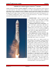
Antares® OSP-3 User’s Guide Preface MEDIUM-CLASS LAUNCH SERVICES FOR THE 21 ST CENTURY ® Orbital Sciences Corporation’s (Orbital’s) Antares is a flight proven two stage launch vehicle designed to provide responsive, cost effective, and reliable access to orbit for Medium-Class payloads.
Antares® OSP-3 User’s Guide Preface The information provided in this Antares OSP-3 user’s guide is for initial planning purposes for OSP-3 payloads only. Information for development/design is determined through mission specific engineering analyses. The results of these analyses are documented in a mission-specific Interface Control Document (ICD) for the spacecraft organization to use in their development/design process.
Antares® OSP-3 User’s Guide Table of Contents PAGE PREFACE .....................................................................................................................................................iv GLOSSARY .................................................................................................................................................. x 1. INTRODUCTION .............................................................................................................................
Antares® OSP-3 User’s Guide Table of Contents 7.4. Payload Processing/Integration .................................................................................................. 57 7.5. Pre-Launch and Launch Operations ........................................................................................... 58 8. ENHANCEMENTS ................................................................................................................................. 60 8.1. Separation Systems ...............
Antares® OSP-3 User’s Guide Table of Contents Figure 3.3-6. Antares 122 and 132 High Energy Performance from WFF ................................................ 14 Figure 3.4-1. Antares Fleet Launch Capabilities from KLC ....................................................................... 15 Figure 3.4-2. Antares 120 Launch Capabilities from KLC ......................................................................... 16 Figure 3.4-3. Antares 121 Launch Capabilities from KLC ..........................
Antares® OSP-3 User’s Guide Table of Contents Figure 8.6-1. The Orbital Team Has Extensive Experience in a Payload Processing Clean Room Environment ................................................................................................................................................ 67 Figure 8.7-1. Antares Secure FTS System Block Diagram ....................................................................... 68 Figure 8.8-1. TDRSS 20W LCT2 Transmitter and UB S-Band Antenna .....................
Antares® OSP-3 User’s Guide Glossary GLOSSARY 6DOF AAC ACS ADS AIM ait ATK ATP BTS C C&C C/No CBOD CCAM CDR CG CLA cm CONOPS COTS CRD CRS CVCM dB deg DIACAP ECS EED EELV EGSE EICD EMC EME EMI F FAA FAB FMA Release 1.1 Six Degrees of Freedom Alaska Aerospace Corporation Attitude Control System Automatic Destruct System Analog Input Module atmospheric interceptor technology Alliant Tech Systems, Inc.
Antares® OSP-3 User’s Guide MDR MECO MES MGSE MHz MICD MIL-STD MIWG mm MRR ms MSPSP mV N2 N NASA NiCd nmi NTO OBV OD ODM OR Orbital OSP-3 P/L PCM PDR PECS PFF PMA PMF POC PPF ppm P-POD PRD Release 1.
Antares® OSP-3 User’s Guide Section 1.0 – Introduction 1. INTRODUCTION The objective of the Antares OSP-3 User’s Guide is to familiarize payload mission planners with Orbital’s Antares launch service as available through the OSP-3 contract. This document provides an overview of the Antares system design and a description of the standard launch services provided to our customers. Orbital also offers a variety of enhanced services to allow maximum flexibility in satisfying customer requirements. 1.1.
Antares® OSP-3 User’s Guide Section 2.0 – Overview 2. ANTARES LAUNCH SYSTEM OVERVIEW Orbital developed the Antares launch vehicle to serve the Medium-Class space launch market, and to provide a cost effective, reliable and flexible means of placing Medium-Class satellites into orbital and Earth-escape trajectories. The Antares design focuses on system reliability, transportability, and minimum on-pad time. 2.1.
Antares® OSP-3 User’s Guide Section 2.0 – Overview The Antares 120 configuration rocket is the baseline for OSP-3. The 130 is an enhancement off that baseline. The Antares 120 and 130 configurations (Figure 2.2-2) utilize the CASTOR 30B and CASTOR 30XL SRM second stage, respectively, to provide Table 2.2-1. Antares Numbering Conventions increased performance to Low Earth Orbit (LEO).
Antares® OSP-3 User’s Guide Section 2.0 – Overview the Antares vehicle, are largely derived from structures and systems used on the Zenit series of launch vehicles, which have extensive flight heritage including more than 60 successful launches. The Stage 1 aft bay contains the MES and is the primary interface between the launch vehicle and ground systems. Many of the mechanical, fluid, and electrical interfaces connect through the aft bay structure.
Antares® OSP-3 User’s Guide Section 2.0 – Overview 2.2.2. Stage 2 Assembly Orbital uses the CASTOR 30 family of SRMs as the second stage for the Antares vehicle (Figure 2.2.21). The CASTOR 30 product line is derived from the heritage CASTOR 120 motor used on the Taurus launch vehicle. The CASTOR 30 motors, manufactured by ATK, consist of a composite graphite/epoxy wound case and a flexseal design at the throat to allow for two-axis Thrust Vector Control (TVC) motion during flight.
Antares® OSP-3 User’s Guide Section 2.0 – Overview 2.2.2.2. Stage 2 Avionics Module The Antares avionics design incorporates Orbital’s latest MACH design technology to provide power transfer, data acquisition, booster interfaces, and ordnance initiation. This advanced system supplies the increased capability and flexibility required by the Antares to communicate with vehicle subsystems, GSE, and the payload utilizing standard Ethernet links and discrete Input/Output (I/O). 2.2.3.
Antares® OSP-3 User’s Guide Section 2.0 – Overview 2.3. Launch Operations While initially based at the Wallops Flight Facility (WFF) in Virginia, The Antares Concept of Operations (CONOPS) as well as all required GSE were developed to be adaptable. With the appropriate fueling infrastructure and pad capability, the Antares launch vehicle and GSE are designed to be compatible with any of the other major Ranges and commercial Spaceports in Alaska, California, and Florida.
Antares® OSP-3 User’s Guide Section 3.0 – Performance 3. PERFORMANCE This section describes the orbital performance capabilities of the Antares vehicle. Antares can deliver payloads to a variety of altitudes and to a range of posigrade and retrograde inclinations. High Energy missions can also be achieved through the addition of an optional STAR 48BV third stage (see Section 8). 3.1.
Antares® OSP-3 User’s Guide Section 3.0 – Performance Figure 3.1.1-1. U.S. Launch Ranges Compatible with Antares Release 1.
Antares® OSP-3 User’s Guide Section 3.0 – Performance Figure 3.2-1. Antares 120 Typical Mission Profile to LEO Release 1.
Antares® OSP-3 User’s Guide Section 3.0 – Performance 3.3. General Performance from WFF Antares general performance for circular orbits of various configurations, altitudes, and inclinations is provided in Figures 3.3-1 through 3.3-5 for launches from WFF. Figure 3.3-1. Antares Fleet Launch Capabilities from WFF Release 1.
Antares® OSP-3 User’s Guide Section 3.0 – Performance Figure 3.3-2. Antares 120 Launch Capabilities from WFF Figure 3.3-3. Antares 121 Launch Capabilities from WFF Release 1.
Antares® OSP-3 User’s Guide Section 3.0 – Performance Figure 3.3-4. Antares 130 Launch Capabilities from WFF Figure 3.3-5. Antares 131 Launch Capabilities from WFF Release 1.
Antares® OSP-3 User’s Guide Section 3.0 – Performance Antares performance for high energy orbits for various configurations utilizing the STAR 48BV enhancement from WFF is provided in Figure 3.3-6. Figure 3.3-6. Antares 122 and 132 High Energy Performance from WFF Release 1.
Antares® OSP-3 User’s Guide Section 3.0 – Performance 3.4. General Performance from KLC For missions requiring greater performance to high inclination polar or sun-synchronous orbits, Antares will launch from KLC located on Kodiak Island, Alaska. Antares estimated performance from KLC for circular orbits of various configurations, altitudes and inclinations is provided in Figures 3.4-1 through 3.4-6. The Antares launch system has been designed for and can be made compatible with the KLC launch site.
Antares® OSP-3 User’s Guide Section 3.0 – Performance Figure 3.4-2. Antares 120 Launch Capabilities from KLC Figure 3.4-3. Antares 121 Launch Capabilities from KLC Release 1.
Antares® OSP-3 User’s Guide Section 3.0 – Performance Figure 3.4-4. Antares 130 Launch Capabilities from KLC Figure 3.4-5. Antares 131 Launch Capabilities from KLC Release 1.
Antares® OSP-3 User’s Guide Section 3.0 – Performance Figure 3.4-6. Antares 122 and 132 Critically Inclined Elliptical Launch Capabilities 3.5. Orbit Insertion Accuracy Orbit insertion errors for any launch vehicle are primarily driven by impulse errors from terminal stage propulsion, payload mass, guidance scheme used, and navigational errors. Orbital characterizes apse errors in terms of altitude errors at the insertion and non-insertion apses.
Antares® OSP-3 User’s Guide Section 3.0 – Performance are also improved to within ±0.08 degrees. When made a targeting priority, RAAN errors are similar to the other configurations at less than 0.2 degrees. Furthermore, this stage allows the explicit targeting of argument of perigee to within ±0.5 degrees. 3.5.3.
Antares® OSP-3 User’s Guide Section 3.0 – Performance 3.6.2. Collision/Contamination Avoidance Maneuver (CCAM) Following orbit insertion and payload separation, the Antares Upper Stage will perform a CCAM. The CCAM minimizes both payload contamination and the potential for recontact between Antares hardware and the separated payload. Orbital will perform a recontact analysis for post-separation events. A typical CCAM begins soon after payload separation.
Antares® OSP-3 User’s Guide Section 4.0 – Payload Environments 4. PAYLOAD ENVIRONMENTS This section provides details of the predicted environmental conditions that the payload experiences during Antares ground operations, powered flight, and post-boost operations. The environmental conditions presented in this section are representative of a typical mission and are applicable to the baseline Antares 120 unless specifically noted.
Antares® OSP-3 User’s Guide Section 4.0 – Payload Environments Table 4.1.1-2 provides the primary dynamic loading events and the time phasing of these events during Antares flight. Pyroshock events are not indicated as they do not occur simultaneously with any other significant dynamic loading events. Table 4.1.1-2.
Antares® OSP-3 User’s Guide Section 4.0 – Payload Environments Figure 4.1.2-1. Nominal Payload Acceleration as a Function of Mass (Antares 120) Figure 4.1.2-2. Nominal Payload Acceleration as a Function of Mass (Antares 121) Release 1.
Antares® OSP-3 User’s Guide Section 4.0 – Payload Environments Figure 4.1.2-3. Nominal Payload Acceleration as a Function of Mass (Antares 122) Figure 4.1.2-4. Nominal Payload Acceleration as a Function of Mass (Antares 130) Release 1.
Antares® OSP-3 User’s Guide Section 4.0 – Payload Environments Figure 4.1.2-5. Nominal Payload Acceleration as a Function of Mass (Antares 131) Figure 4.1.2-6. Nominal Payload Acceleration as a Function of Mass (Antares 132) Release 1.
Antares® OSP-3 User’s Guide Section 4.0 – Payload Environments 4.2. Payload Vibration Environment The random vibration environment at the payload interface is encompassed by acoustics and coupled loads analysis results. Antares does not have a specific random vibration environment for the payload. 4.2.1. Payload Acoustic Environment The maximum expected acoustic levels within the Antares fairing are shown in Figure 4.2-1.
Antares® OSP-3 User’s Guide Section 4.0 – Payload Environments 4.2.2. Sine Vibration Figure 4.2.2-1 defines the maximum flight level payload interface sinusoidal vibration levels for a fixed base payload test, which may be used for preliminary design. The spectrum defined in this figure is provided for reference only. Orbital develops a mission-specific sine spectrum for each mission using the results from CLA. Figure 4.2.2-1. Antares Payload Interface Sine Vibration Levels Release 1.
Antares® OSP-3 User’s Guide Section 4.0 – Payload Environments 4.3. Payload Shock Environment The maximum shock response spectrum at the base of the payload from all launch vehicle events will not exceed the flight limit levels provided in Figure 4.3-1. The flight limit levels are derived from ground separation test data and analytical predictions for the vehicle and payload separation systems.
Antares® OSP-3 User’s Guide Section 4.0 – Payload Environments 4.4. Contamination and Environmental Control Orbital understands the importance of maintaining proper thermal and contamination control and is committed to providing environments that meet customer requirements. Orbital partners with each USAF payload customer to ensure the required payload environments are identified and maintained at all times. Orbital has developed a general environmental control plan for all Antares missions.
Antares® OSP-3 User’s Guide Section 4.0 – Payload Environments system, all which are located within the payload fairing compartment downstream of the payload, are cleaned to visibly clean. 4.4.4. Enhanced Thermal and Contamination Services Orbital recognizes that some payloads may have more stringent cleanliness requirements than those provided by the Standard Launch Service. Orbital offers a variety of enhancements to address these needs. These options are discussed in more detail in Section 8: 4.5.
Antares® OSP-3 User’s Guide Section 4.0 – Payload Environments 4.7. Payload RF Environment As shown in Table 4.7-1, Antares has five RF sources: three S-Band transmitters at 2241.5, 2269.5, and 2288.5 MHz, respectively, and a C-Band Transponder that transmits at 5765 MHz. The fairing provides attenuation for the payload RF environment produced by the external aft antennas until the fairing is deployed.
Antares® OSP-3 User’s Guide Section 5.0 – Payload Interfaces 5. PAYLOAD INTERFACES This section describes the available mechanical, electrical and GSE interfaces between the Antares launch vehicle and the payload. 5.1. 3.9 Meter Payload Fairing The Antares payload fairing encloses the payload and provides protection and contamination control during ground handling, integration and flight. The Antares payload fairing is a 3.9 m (155 in.
Antares® OSP-3 User’s Guide Section 5.0 – Payload Interfaces Figure 5.1.1-1. Antares Fairing Dynamic Payload Envelope with 1575 mm Mechanical Interface Release 1.
Antares® OSP-3 User’s Guide Section 5.0 – Payload Interfaces Figure 5.1.2-1. Antares Fairing Standard Access Door Location 5.2. Payload Mechanical Interface and Separation System Antares provides for a standard non-separating payload interface. Orbital will provide all flight hardware and integration services necessary to attach non-separating and separating payloads to the Antares launch vehicle. Payload ground handling equipment is typically the responsibility of the payload contractor.
Antares® OSP-3 User’s Guide Section 5.0 – Payload Interfaces 5.2.1. Non-Separating Payload Interface Orbital provides non-separating payloads or payloads with customer-provided separation systems with a 1575 mm (62 in.) diameter bolted interface shown in Figure 5.2.1-1. The 1575 mm (62 in.) diameter payload mounting surface provides a butt joint interface with 120 holes designed to accommodate SAE ¼ inch fasteners. The 1575 mm (62 in.
Antares® OSP-3 User’s Guide Section 5.0 – Payload Interfaces 5.2.3. Mechanical Interface Control Drawing (MICD) All mechanical interfaces between the payload and Antares are defined in the mission ICD and a missionspecific MICD. The MICD is a dimensional drawing that captures the payload interface details, separation system, payload static volume within the fairing, and locations of the access doors.
Antares® OSP-3 User’s Guide Section 5.0 – Payload Interfaces Payload Telemetry: The Antares telemetry subsystem provides dedicated payload discrete and analog telemetry monitors through dedicated channels (up to 24) on the Avionics MACH encoder. In addition, the Avionics MACH Controller Module has the capability to transmit payload data up to 10 kb/s. The MACH Encoder serial interface uses an IRIG standard RS-422 driver interface providing a simple, configurable payload interface definition.
Antares® OSP-3 User’s Guide Section 5.0 – Payload Interfaces The lateral offset of the payload center of mass is constrained by the payload separation tip-off requirements and the structural capability of the particular separation system. If preliminary design assessments indicate that the lateral center of gravity offset of the payload may exceed one inch, the customer is encouraged to contact the Antares Program Office to verify the feasibility of achieving the specific payload tip-off requirements. 5.
Antares® OSP-3 User’s Guide Section 5.0 – Payload Interfaces 5.4.5. Payload Dynamic Frequencies To avoid unfavorable dynamic coupling of the payload with the launch vehicle dynamic forcing functions, the payload should be designed with a structural stiffness to ensure that the payload structure first mode fundamental frequency is greater than 20 Hz axially (thrust axis) and above 8 Hz in the lateral axes.
Antares® OSP-3 User’s Guide Section 6.0 – Mission Integration 6. MISSION INTEGRATION Orbital’s first and foremost consideration is to provide a successful mission with an absolutely safe and reliable launch service for our customers. Orbital’s established engineering, production, testing, and quality assurance approaches are designed to ensure these considerations. Another Orbital top priority is to ensure timely launch services, with emphasis on maintaining high schedule confidence and flexibility.
Antares® OSP-3 User’s Guide Section 6.0 – Mission Integration Orbital establishes a mission-unique organizational structure on each Antares launch service to manage and execute key mission roles and responsibilities. The Mission Management Office provides the direct interface to our customers and ensures the requirements of each mission are satisfied. The integrated Antares organizational structure, as shown in Figure 6.
Antares® OSP-3 User’s Guide Section 6.0 – Mission Integration 6.1.2. Orbital Mission Responsibilities Orbital’s mission responsibilities fall into four primary areas: Program Management, Mission Management, Mission Engineering, and Launch Site Operations. Key positions and responsibilities of the Launch Service Team are provided in Figure 6.1.2-1 and detailed below. 6.1.2.1.
Antares® OSP-3 User’s Guide Section 6.0 – Mission Integration 6.1.2.3. Antares Mission Engineering The Mission Engineer provides technical support to the Mission Manager and is the technical focal point to the customer and payload teams to ensure that the Antares vehicle satisfies all payload requirements.
Antares® OSP-3 User’s Guide Section 6.0 – Mission Integration The typical Mission Cycle interweaves the following activities: a. Mission management, document exchanges, meetings, and formal reviews required to coordinate and manage the launch service. b. Mission analyses and payload integration, document exchanges, and meetings. c. Design, review, procurement, testing and integration of all mission-peculiar hardware and software. d.
Antares® OSP-3 User’s Guide Section 6.0 – Mission Integration 6.3. Mission Integration Process Orbital uses a successfully proven approach to mission integration management. The core of the mission integration process consists of a series of Mission Integration Working Groups and Range Working Groups. 6.3.1. Mission Integration Working Group (MIWG) Orbital conducts quarterly MIWGs from the onset of the mission through launch (Table 6.3.1-1).
Antares® OSP-3 User’s Guide Section 6.0 – Mission Integration 6.3.3. Mission Reviews In addition to the MIWG and RWG, a number of mission reviews are conducted as required to ensure the launch service and payload integration activities are progressing according to schedule. During the integration process, mission reviews are held to provide coordination with a broader audience of mission and management participants who do not participate in either of the Working Groups.
Antares® OSP-3 User’s Guide Section 6.0 – Mission Integration the following paragraphs, is critical for enabling the Orbital team to perform our responsibilities and prepare for and manage the Antares launch of the payload. The documentation delivery requirements are included in the Integrated Master Schedule. 6.3.4.1.
Antares® OSP-3 User’s Guide Section 6.0 – Mission Integration 6.3.4.6. Mission ICD Verification Documentation Orbital conducts a rigorous verification program to ensure all requirements on both sides of the launch vehicle-to-payload interface have been successfully fulfilled. As part of the ICD, Orbital includes a verification matrix that indicates how each ICD requirement will be verified (e.g., test, analysis, demonstration, etc.).
Antares® OSP-3 User’s Guide Section 6.0 – Mission Integration 6.3.5.2. Mission ICD Verification Documentation Orbital conducts a rigorous verification program to ensure all requirements on both sides of the launch vehicle-to-payload interface have been successfully fulfilled. Like the customer-provided verification data discussed in Section 6.3.4.6, Orbital will provide the customer with data for all interfaces that are the responsibility of the launch vehicle to verify.
Antares® OSP-3 User’s Guide Section 6.0 – Mission Integration 6.3.5.9. Mission Constraints Document (MCD) This Orbital-produced document summarizes launch day operations for the Antares launch vehicle as well as for the payload.
Antares® OSP-3 User’s Guide Section 7.0 – Ground and Launch Operations 7. GROUND AND LAUNCH OPERATIONS Antares ground and launch operations are conducted in three major phases: Launch Vehicle Processing/Integration: Includes receipt and checkout of the launch vehicle components, followed by assembly and test of the Antares vehicle.
Antares® OSP-3 User’s Guide Section 7.0 – Ground and Launch Operations 7.2. Antares Processing and Launch Facilities at WFF As a baseline, Antares will be launched from the NASA WFF in Virginia. As an option, Antares can be launched from KLC in Alaska. At WFF, the vehicle is assembled and processed in the HIF, Building X-79. The HIF is shown in Figure 7.2-1. The HIF includes an extensive vehicle integration and test area with two bridge cranes.
Antares® OSP-3 User’s Guide Section 7.0 – Ground and Launch Operations Pad 0A on the TEL and its associated transporters. At the launch pad, the hydraulic erector system interfaces with the TEL strongback and rotates the LV to vertical and positions it for mate to the launch mount. Vehicle electrical, mechanical, and hydraulic connections are mated and checked, including payload pass through connections to payload GSE. The TEL also serves as the launch tower, retracting just prior to liftoff. 7.2.1.2.
Antares® OSP-3 User’s Guide Section 7.0 – Ground and Launch Operations 7.2.2.1. Antares Launch Pad at WFF Antares missions from WFF will launch from Launch Pad 0A, illustrated in Figure 7.2.2.1-1. The launch pad and launch site are owned and operated by MARS and provide the facilities and infrastructure required to support the erection, fueling, final checkout, and launch of the Antares integrated launch vehicle.
Antares® OSP-3 User’s Guide Section 7.0 – Ground and Launch Operations Antares launch vehicle control, Antares fueling control, payload control, Range Safety, and WFF site control (i.e., propellant farm, ECS, and telemetry, power, and network support equipment). 7.2.2.3. Mission Control Center (MCC) and Range Control Center (RCC) The MCC/RCC, shown in Figure 7.2.2.3-1, serves as the launch authority center for Antares launches.
Antares® OSP-3 User’s Guide Section 7.0 – Ground and Launch Operations 7.3. Launch Vehicle Processing All major vehicle subassemblies are delivered from either Orbital’s production facilities or directly from the vendor to the HIF. Figure 7.3-1 depicts the typical flow of hardware from the factory to the launch site. Once the major vehicle components and subassemblies are delivered to the HIF, the vehicle is horizontally integrated and tested prior to the arrival of the payload.
Antares® OSP-3 User’s Guide Section 7.0 – Ground and Launch Operations 7.3.2. Stage 2 Motor The Stage 2 solid rocket motor is received via overland transporter and transferred to its MGSE dolly in the HIF using the HIF cranes. Mechanical, electrical, and ordnance installation is performed followed by Thrust Vector Actuator (TVA) performance testing. The avionics section, which is shipped as an assembly from Orbital, is attached to the forward ring of the Stage 2 motor.
Antares® OSP-3 User’s Guide Section 7.0 – Ground and Launch Operations final flight pressure, and final safe and arm verification testing. The vehicle and launch team are then ready for roll-out to the pad in preparation for countdown and launch. 7.5. Pre-Launch and Launch Operations Prelaunch activities begin at approximately L-3 days with transportation of the integrated launch vehicle from the HIF to the launch complex.
Antares® OSP-3 User’s Guide Section 7.0 – Ground and Launch Operations using abbreviated timelines. All aspects of the team’s performance are exercised, as well as simulated holds, scrubs, and recycle procedures. The operations and team performance are evaluated and lessons learned are incorporated prior to the MDR. The MDR is performed 2 days before vehicle roll-out to certify the launch team’s readiness for launch.
Antares® OSP-3 User’s Guide Section 8.0 – Non-Standard Services 8. ENHANCEMENTS The Antares launch service is structured to provide a standard launch service that can then be augmented with optional non-standard services to meet the specific needs of individual customers. These optional capabilities are defined within this Section. Should a customer have mission-unique requirements not addressed in this section, please contact the Antares Program Office directly for further assistance. 8.1.
Antares® OSP-3 User’s Guide Section 8.0 – Non-Standard Services Figure 8.1.1-2. Antares 937S Payload Dynamic Envelope Release 1.
Antares® OSP-3 User’s Guide Section 8.0 – Non-Standard Services 8.1.2. RUAG 1194VS Separation System The Antares launch vehicle standard 1575 mm (62 in.) interface allows use of the standard RUAG PAS47VS Payload Adapter System. This 47‖ marmon clamp and adapter cone separation system has extensive launch heritage, having flown on Ariane, Atlas, Delta, Proton and other launch vehicles.
Antares® OSP-3 User’s Guide Section 8.0 – Non-Standard Services Figure 8.1.2-2. Antares 1194VS Payload Dynamic Envelope Release 1.
Antares® OSP-3 User’s Guide Section 8.0 – Non-Standard Services 8.1.3. RUAG 1666VS Separation System The Antares launch vehicle standard 1575 mm (62 in.) interface allows use of the standard RUAG PAS66VS Payload Adapter System. This 66‖ marmon clamp and adapter cone separation system has extensive launch heritage, having flown on Ariane, Atlas, Delta, Proton and other launch vehicles.
Antares® OSP-3 User’s Guide Section 8.0 – Non-Standard Services Figure 8.1.3-2. Antares 1666VS Payload Dynamic Envelope Release 1.
Antares® OSP-3 User’s Guide Section 8.0 – Non-Standard Services 8.2. Conditioned Air Conditioned air is included in the baseline vehicle cost and is described previously in Section 4.4. The Nitrogen Purge and Enhanced Contamination Control enhancements complement this capability as described in the enhancements in Section 8.3 and 8.6. 8.3. Nitrogen Purge As an enhancement, Orbital provides a gaseous nitrogen purge to the payload after fairing encapsulation through lift-off.
Antares® OSP-3 User’s Guide Section 8.0 – Non-Standard Services 8.6. Enhanced Contamination Control To meet the requirement for a low contamination environment, Orbital uses existing processes developed and demonstrated on the Minotaur, Taurus, and Pegasus programs. These processes are designed to minimize outgassing, supply a Class 10,000 (ISO 7) clean room environment, assure a high cleanliness payload envelope, and provide a HEPA-filtered, controlled humidity environment after fairing encapsulation.
Antares® OSP-3 User’s Guide Section 8.0 – Non-Standard Services Propyl Alcohol (IPA), HEPA filtered vacuums, etc.) to clean the fairing surfaces to meet the requirements. When the fairing is not in use, it is covered with an appropriate cleanroom compatible material to maintain cleanliness. 8.7. Secure FTS The Secure FTS is achieved with the L-3 Cincinnati Electronics Model CRD-120/205 LV Command Receiver Decoder (CRD) that is compatible with the "High-Alphabet" range safety modulation format.
Antares® OSP-3 User’s Guide Section 8.0 – Non-Standard Services batteries that are used on other subsystems. The RF network, including the antennas and couplers, are also directly leveraged and common with the existing Antares FTS subsystem. Skin mounted external antennas mounted on the interstage are employed from pre-launch through interstage separation. Following interstage separation, stand-off plate-mounted antennas on the ACS deck are used through end of mission. 8.8.
Antares® OSP-3 User’s Guide Section 8.0 – Non-Standard Services 8.9. Increased Insertion Accuracy Orbital offers the Antares Bi-Propellant Third Stage (BTS), shown in Figure 8.9-1, as an enhancement to improve insertion accuracy as well as to provide increased orbital performance capability. The BTS design is derived from the flight proven satellite kick stage currently flown on Orbital’s STAR™ bus Geosynchronous (GEO) satellites.
Antares® OSP-3 User’s Guide Section 8.0 – Non-Standard Services Figure 8.10-2. Use of Soft Ride Significantly Attenuates Peak LV Dynamic Environments 8.11. Debris Mitigation System No Debris Mitigation System is offered for Antares. LEO orbits requiring debris mitigation have the performance included in the BTS described in Section 8.9. Other debris mitigation systems will be designed on a mission specific basis, if required. 8.12.
Antares® OSP-3 User’s Guide Section 8.0 – Non-Standard Services Figure 8.13-1. Antares LV Enhanced Performance Options 8.13.2. Antares STAR 48BV Third Stage Orbital offers the STAR 48BV SRM as a high energy third stage on Antares shown in Figure 8.13-1. The 3-axis stabilized STAR 48BV third stage provides a significant performance increase to achieve elliptical orbits or Earth-escape trajectories, as shown in Sections 3.3 and 3.4.
Antares® OSP-3 User’s Guide Section 8.0 – Non-Standard Services 8.14. Lengthened Payload Envelope As an enhancement, Orbital provides additional fairing adapters for the Antares 120 series vehicles consisting of 2774 mm (97.4 in.) tall composite cylinders inserted at the base of the standard fairing, effectively increasing the length of the payload static envelope by an equivalent amount (Figure 8.141).
Antares® OSP-3 User’s Guide Section 8.0 – Non-Standard Services Figure 8.15-1. Typical Propellant Loading Schematic 8.17. Poly-Pico Orbital Deployer (P-POD) Orbital offers to fly a single P-POD canister mounted to the Stage 2 motor as an enhanced Antares service for 120 or 130 configurations.
Antares® OSP-3 User’s Guide Section 8.0 – Non-Standard Services launches from KLC having conducted the first ever launch from KLC on the atmospheric interceptor technology (ait) program, multiple target vehicles, and two successful Minotaur IV vehicles. The layout of the Antares facilities at KLC is provided in Figure 8.19-1. The launch pad design is nearly identical to the Antares pad at WFF. The HIF design, while resized to meet the expected launch rate, fully meets Antares requirements. Figure 8.19-1.
Antares® OSP-3 User’s Guide Appendix A – Payload Questionnaire APPENDIX A PAYLOAD QUESTIONNAIRE Release 1.
Antares® OSP-3 User’s Guide Appendix A – Payload Questionnaire SPACECRAFT IDENTIFICATION FULL NAME: ACRONYM: OWNER/OPERATOR: INTEGRATOR(s): ORBIT INSERTION REQUIREMENTS* SPHEROID Standard Other: ALTITUDE Insertion Apse: Opposite Apse: ± km ± km ± nmi ± nmi or... Semi-Major Axis: Eccentricity: ± km e ± nmi INCLINATION ± deg ORIENTATION Argument of Perigee: Longitude of Ascending Node (LAN): ± deg Right Ascension of Ascending Node (RAAN): ± ± deg deg...
Antares® OSP-3 User’s Guide Appendix A – Payload Questionnaire GROUND SUPPORT EQUIPMENT Describe any ground support equipment, mission control facilities (e.g.; LCC, MCC) and Range facilities (e.g., Launch Equipment Vault (LEV) which the Spacecraft intends to use: LEV Describe (in the table below) Spacecraft EGSE to be located in the LEV. Approximate Size (LxWxH) Equipment Name / Type Release 1.
Antares® OSP-3 User’s Guide Appendix A – Payload Questionnaire EARLY ON-ORBIT OPERATIONS Briefly describe the spacecraft early on-orbit operations, e.g.
Antares® OSP-3 User’s Guide Appendix A – Payload Questionnaire SPACECRAFT PHYSICAL DIMENSIONS STOWED CONFIGURATION in cm in cm Length/Height: Diameter: Other Pertinent Dimension(s): Describe any appendages/antennas/etc which extend beyond the basic satellite envelope: ON-ORBIT CONFIGURATION Describe size and shape: If available, provide electronic files of dimensioned drawings for both stowed and on-orbit configurations.
Antares® OSP-3 User’s Guide Appendix A – Payload Questionnaire ASCENT TRAJECTORY REQUIREMENTS Free Molecular Heating at Fairing Separation: FMH = W/m 2 2 Btu/ft /hr Fairing Internal Wall Temperature T = deg C Dynamic Pressure at Fairing Separation: q = N/m 2 lbf /ft Ambient Pressure at Fairing Separation: P = N/m 2 lbf /in 2 lbf /in /sec ΔP = Maximum Pressure Decay During Ascent: N/m /sec deg F 2 2 2 Thermal Maneuvers During Coast Periods: SPACECRAFT ENVIRONM
Antares® OSP-3 User’s Guide DIAMETER Appendix A – Payload Questionnaire MECHANICAL INTERFACE Describe Diameter of Interface (e.g. Bolt Circle, Separation System, etc.
Antares® OSP-3 User’s Guide Appendix A – Payload Questionnaire ELECTRICAL INTERFACE Bonding Requirements: Are Launch Vehicle Supplied Pyro Commands Required? Yes / No If Yes, magnitude: amps for When ________ seconds before separation Are Launch Vehicle Supplied Discrete Commands Required? If Yes, describe: msec Yes / No Is Electrical Access to the Satellite Required? After Encapsulation? At Launch Site? Is Spacecraft Battery Charging Required? After Encapsulation? At Launch Site? Is a Telemetry Interf
Antares® OSP-3 User’s Guide Appendix A – Payload Questionnaire REQUIRED PASS-THROUGH SIGNALS Item No. Pin Signal Name From LEV To Satellite Shielding Max Current (amps) Total Line Resistance (ohms) 1 2 3 4 5 6 7 8 9 10 11 12 13 14 15 16 17 18 19 20 21 22 23 24 25 26 27 28 29 30 REQUIRED PASS-THROUGH SIGNALS Release 1.
Antares® OSP-3 User’s Guide Item No. Pin Signal Name Appendix A – Payload Questionnaire From LEV To Satellite Shielding Max Current (amps) Total Line Resistance (ohms) --- --- --- --- --- 31 32 33 34 35 36 37 38 39 40 41 42 43 44 45 46 47 48 49 50 51 52 53 54 55 56 57 58 59 60 --- Reserved for separation loop REQUIRED PASS-THROUGH SIGNALS Release 1.
Antares® OSP-3 User’s Guide Item No. Pin 61 --- Signal Name Reserved for separation loop Appendix A – Payload Questionnaire From LEV To Satellite Shielding Max Current (amps) Total Line Resistance (ohms) --- --- --- --- --- 62 63 64 65 66 67 68 69 70 71 72 73 74 75 76 77 78 79 80 81 82 83 84 85 86 87 88 89 90 91 REQUIRED PASS-THROUGH SIGNALS Release 1.
Antares® OSP-3 User’s Guide Item No. Pin Signal Name Appendix A – Payload Questionnaire From LEV To Satellite Shielding Max Current (amps) Total Line Resistance (ohms) 92 93 94 95 96 97 98 99 100 101 102 103 104 105 106 107 108 109 110 111 112 113 114 115 116 117 118 119 120 121 --- Reserved for separation loop --- --- --- --- --- 122 --- Reserved for separation loop --- --- --- --- --- Release 1.
Antares® OSP-3 User’s Guide Appendix A – Payload Questionnaire This page intentionally left blank. Release 1.