
User guide

129
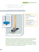
> Model Towers
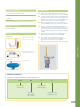
supplied accessories
>
CD-ROM Documentation Set:
User Manual (Installation, Setup, Operation & Maintenance)
>
Cables:
Cable Carrier
Interconnect Cable for Connection to Lower Positioner
optional accessories
Lower Positioner
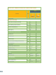
options
Option 001
Option 002
Option 003
technical notes
1 Model tower height is defi ned as the distance from
the base of the offset slide to the center of the roll axis.
2 The lower positioner may require electrical wiring and/
or an RF path to support the model tower. Options are
available for the lower positioner, including EX002, SR,
and RJ. Lower positioner purchased separately.
3 All accuracy data is based on no-load conditions.
Contact ORBIT/FR for accuracy under load conditions.
4 Roll axis is equipped with adjustable limit switches
capable of approx 20° to 900° total travel. When rotary
joint options are specifi ed, limit switches remain but
are electrically disabled. Roll axis is factory-set at 400°
(± 200°).
5 Rotary joint options may alter the original physical
profi le of the roll axis stage. Consult ORBIT/FR.
6 Verify model tower’s maximum swing radius
(G - clearance to absorber) when specifying this
product for use inside an anechoic chamber.
7 Dimensions may vary depending on fi nal confi guration.
• Foam Bracket w/ Interface
Plate, Up to 4.4 lbs (2 kg)
• Portable Triangular Base Plate
(Increases Overall Height)
• Absorber Platter
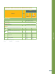
ORDERING INFORMATION
• Build your confi guration using the ordering example below.
DBDR MD 21 60
Basic Model
Tower Series
Linear Offset
Slide Travel (in)
Capacity:
MD - Medium
HD - Heavy
Total Roll-to-Base
Height (in or mm)
---