21cm
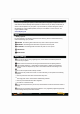
Introduction Thank you for purchasing our product, an ideal radio system for beginners or experienced users alike. Read this manual carefully before operation in order to ensure your safety and the safety of others or the safe operation of your system. If you encounter any problem during use, refer to this manual first. If any problem persists, contact your local dealer or visit our service and support website for help : www.hobbyking.com Safety 1.
� Do not touc h any part of the model that may generate heat during operation. The engine, motors and s peed controller may be hot and cause injury. � Do not g ras p the transmitter's antenna during flight. It may be deg rade the quality of the radio frequenc y transmis sion. 0 Make s ure the model flies within a certain range. FCC statement This device comp lies with par t 15 of the FCC Rules . Operation is subject to the following tw o cn nditions: 1.
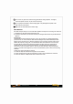
Transmitter Overview S6 , S8 S5 S7 S2 S3 S4 S1 Lanyard hook Throttle/Rudder Elevator/Aileron Elevator trim Thro ttle trim Aileron trim Rudder trim Binding key Wheel Cancel key Power On/Off LCD ----------------- Antenna ------Trainer port 1-------MicroUSB port =======-- Grip ----- Battery compartment Installation and removal of the transmitter battery The Tx10i transmitter is designed to work with four x (LR6) AA alkaline dry cell batteries � '"""' .. •••••••••7x1a= I � "-' .,.
Binding procedure 1. Initiate binding procedure on your receiver (depend s on the receiver used - bind plug, button, auto-bind. To see how to initiate binding on the receiver please refer to the receiver manual). 2. Press and hold the binding key and turn on the transmitter. (Or, turn on the transmitter, press and hold the wheel to enter the main menu to select model setup, then choose the bind menu to enter binding mode) . •••••••••••7x 1a= � '"""' � "-' .,.
3. The system will display "RX Binding.:'. After successfully binding, the transmitter will automatically exit this binding menu. 4. If your receiver uses a bind plug for binding make sure you remove it after binding procedure. NOTICE: Remove the bind plug to prevent the system from entering bind mode the next time the power is turned on. Sometimes servo inputs or ESCs with high input load can cause receiver binding in "No telemetry" mode.
End points End points allow you to control the lower and upper travel limits for each servo. For each channel the user can set the lower and upper limits. Adjustment can be made for any channel. End points End points Chl Ch2 Ch3 Ch-4 Ch5 Ch6 +100::-:: 100::-:: 100::-:: 100::-:: 100::-:: 100::-:: 100::-:: 100::-:: 100::-:: 100::-:: 100::-:: 100::-:: Ch7 +100::-:: 100::-:: Ch8 100::-:: Ch9 100::-:: Ch10 100::-:: 100::-:: 100::-:: 100::-:: Setup: 1. Press the Roller button to select channel . 2.
Dual rate/ exponential (exp.) Dual rate changes the servo travel for a control surface on RIC aircraft (Ailerons, Elevator and Rudder). Dual rate consists of Low rates and High rates. Low rates make the aircraft less responsive (i.e. easier to control), and High rates make the aircraft more responsive (i.e. harder to control). Dual rates are controlled by a selected switch (S1 to S8).
Main menu Servo setup Dual rate/exp. +Throttle curve Throttle cut Mixes Range test Setup: 1. Select "Throttle curve" in main menu. 2. Press the Roller button to select point L, 1, 2, 3, H. 3. Move the wheel left or right to change the point's value (position) on the graph. 4. Press and hold the wheel to save and exit , or press the cancel key to exit without saving. =Throttle curve= Normal L+ 01/. 1 251/. 2 501/. 3 751/. H 1881/.
Mixes This function is used to create a mix between channels. For example, if at low throttle some automated flap movement is desired, it is possible to create a mix to do this. Main menu Servo setup Dual rate/exp. Throttle curve Throttle cut +Mixes Range test Setup: 1. Select "Mixes" in main menu. 2. Press the roller button to select below options: • Mix#: 1 to 6 • Mix is: on/ off • Master: Channel 1 to 6 • Slave: Channel 1 to 6 • Pos. mix: -100% to 100% • Neg. mix: -100% to 100% • Offset: -50% to 50% 3.
2.Press and hold the Binding key to activate Range test . Range test FULL POWER Press and hold the BINDING key to acti vate Range test.Dis tance = 30 paces/ 30 meters. Timer This function is used to keep track of time in order to to reduce the risk of aircraft running out of battery/fuel and crashing. Timers are very useful when used in conjunction with a toggle. There are two choices for timer: "Engine timer" and "Multi. timer" Engine timer counts the time when throttle value exceeds the set value.
Up Mode: • Reset - Press and hold the cancel key to reset the timer if needed, then press the Roller button. • Thr. pos - Turn the Roller button to change the throttle trigger point. • Press and hold the Roller button to save and exit, or press the cancel key to exit without saving. Down Mode: • Reset - Press and hold the cancel key to reset the timer if needed, then press the Roller button. • Thr. pos - Turn the Roller button to change the throttle trigger point.
• Reset Switch-Turn the Roller Button to reset the switch 1 to 8 or None to position up, middle or down. • Press and hold the Roller button to save and exit , or press the cancel key to exit without saving. Down and up Mode: • Timer State-Turn the Roller button to select "Stop" or "Run". If "Run"is selected, the timer is counting up. • Reset - Press and hold the cancel key to reset the timer if needed, then press the Roller button. • Set up -Turn the Roller button to set the time in min. and sec.
RX: This setting is used to sound an alarm when the receiver battery voltage drops dangerously low. =setup sensors= +RX Min Alarm 4.3U OFF Max OFF 8. 1U BATT: This setting is used to sound an alarm when the voltage is out of range. =setup sensors= +BATT Min Alarm O.OU OFF Max Alarm SO.OU OFF TEMP: Temperature information comes from an optional Temperature sensor. If it becomes higher or lower than the set value, an alarm will alert you.
Aux. channels This function allows users to set auxiliary channels. Every channel that is not assigned during the model setup will be set as an AUX channel. AUX channels can be used to control various extra features on an aircraft including landing gear, brakes, lights. Setup: 1. Press the wheel to change source from aux channel 5 to 10 (And after channels not in use) . 2. Move the wheel to assign a switch. 3. Press and hold the wheel to save and exit, or press the cancel key to exit without saving. =Aux.
THR AIL ELE RUD AX1 AX2 Display AX3 AX4 AX5 AX6 Display Model Setup The Model setup function is used to set up, manage and delete models. Model Select: Selects a model from memory. 1. Use the wheel to select a memory slot for the model. 2. Press and hold the wheel to save and exit, or press the cancel key to exit without saving. Model setup +Model select Type select Model name Model reset Model copy Flaps Type select: Change between airplane/ glider, and different helicopter types and multicopter. 1.
Model Reset: Resets a model to factory default settings. 1. Use the wheel to select a memory slot for the model. 2. Press the wheel to select and then move the wheel to select yes and press the wheel again. 3. If needed press the cancel key to exit without saving. Model reset +Model 01 Model-01 "OK" to reset Model copy: Copies a model from one memory slot to another. 1. Use the wheel to select a model to copy and press the wheel. 2. Use the wheel to select a memory slot to copy to. 3.
Elevon: The elevon function is used for planes that combine the elevons and ailerons together. Setup: 1 . Use the wheel to enable the elevon function and press the wheel. 2. Use the wheel to set the first channel's position and press the wheel. 3. Use the wheel to set the second channel's position. 4. Press and hold the wheel to save and exit, or press the cancel key to exit without saving.
•Go to Flaperon section. • Sw: - enable and assign available switc h to turn flaperon On and O f f (Sw 1 .. Sw8). • A djust position o f ailerons in Flaperon mode setting percentage (-100%~+100%). • Positive percentage moves aileron in "flaps" position in one direction, while ne gative percentage moves them in opposite direction. You should use negative or positive values depending on your model setup. Percentage of the flaps is taken from the aileron servo travel set in Dual Ail section.
Model setup Swashplate mix Adjust the motion range of the three inputs(aileron, elevator, pitch) to achieve the desired maneuverability. Refer to your model's manual to ensure the best results. This function is used to edit the pre-programmed mix control of the helicopter's aileron, elevator and pitch. Use the wheel to change the aileron, elevator and pitch values. Setup: 1. Use the wheel to change the aileron value, then press the wheel. 2. Use the wheel to change the elevator value, then press the wheel.
ARM The function ensures a model will not fly until a switch has been toggled. Setup: 1. Use the wheel to assign a switch or toggle to ON (always ON) , then press the wheel. 2. Use the wheel to select a channel. 3. Press and hold the wheel to save and exit, or press the cancel key to exit without saving. ARM +Sw = Disabled Ch=5 System setup User name Set a user name for your system. Setup: 1. Use the wheel to select a character and press the wheel to enter it. 2.
Student mode This function is used when another system is connected as a master (trainer). When this mode is active all settings will be bypassed and the system will only function through the master. Press and hold the wheel and move the wheel to select yes. =student mode= This wi11 enter student mode all settings will be bypassed Press "OK" to confirm Sticks mode There are 4 available stick modes, each stick mode changes the stick functions.
System settings Firmware Ver. This function shows information about the transmitter 's currently installed firmware version. =Firmware ver. = ORX Tx10i 1.0 15-Jan-2018 Hardware lJ_1.5 Firmware update The function is for updating the system's firmware. Setup: 1. Download the latest firmware from www.hobbyking.com 2. Open the firmware update on a computer and connect the system via USB cable. 3. Select [Firmware Update] from the systems function menu.
RF module update This function is for updating the RF module. Setup: 1. Connect the system to your computer via USB cable. 2. Press the wheel, the system will show a prompt, "This will enter RF module update mode and halt other functions" with an option to continue. Press Roller button and the screen will show "Yes" and "No". Select "Yes" and press Roller button to confirm. 3. Open the software update on a computer . Select COM port, then press "Connect". 4.