
Instructions


9
3.2
3.1
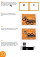
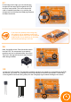
Locate the green and red LEDs. The LEDs are polarity sensitive and need to be inserted into the PCB
the correct way round. We can use a similar method to the electrolytic capacitors to determine the
correct orientation. The positive (anode) is the longer leg and the negative (cathode) is the shorter leg.
Match the longer leg with the + mark on the PCB. It doesn’t matter which LED you solder in which
location.
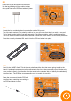
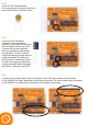
Locate the ICSP 6 pin header. This is not polarity
sensitive, but you will notice that the legs either side
of the black plastic are dierent lengths. The shorter
ends should be on the underside of the boards with
the longer ends accessible from the top.
3.3
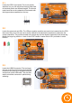
Locate the USB-B connector. The two larger
pins act as anchor points and ensure that the
connector can stand up to repeated insertion
and removal of the USB cable. They are also
useful to hold the connector in place during
soldering.