
Instructions


6
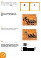
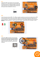
2.6
Locate the 7805 voltage regulator (L7805CV).
Just like the diode the voltage regulator needs
to be placed in the PCB the correct way round.
The diagram on the right shows the pinout.
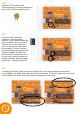
2.5
Place the 22pF (22) capacitors into the marked
locations on the PCB and solder in place.
2.4
Place the 0.1uF (104) capacitors into the
marked locations on the PCB and solder in
place.
Output
GND
Input
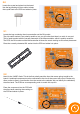
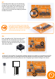
2.3
Separate the ceramic capacitors from the
other components. The 0.1uF capacitors are
marked with the number 104 and the 22pF
are marked with the number 22.
5x 2x
0.1uF 22pF