
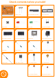
Instructions


5
2.0
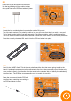
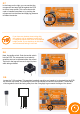
Locate the crystal and place into the board.
Use the leg bending tip from earlier to keep
the crystal ush to the PCB and solder in place.
2.1
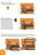
Locate the bag containing the microcontroller and the DIL socket.
The chip carrier socket is not polarity sensitive, but you will notice that there is a notch in one end.
This is used to assist with the correct placement of the Microcontroller, which is polarity sensitive.
The PCB, the DIL socket and the Microcontroller all share the notch marking to aid correct placement.
Place the correctly orientated DIL socket into the PCB and solder into place.
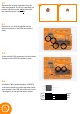
2.2
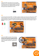
Place the component into the PCB with
the silver band matching the marking on
the PCB and solder in place.
Next it’s the 1N4007 diode. This is the rst polarity sensitive item that we are going to add to the
board. A polarised component must be connected to the circuit the correct way round. Diodes only
allow current to ow in one direction from the anode to the cathode. We can identify the cathode by
the silver band. The PCB has a corresponding mark to match this up with.