
User Manual

O
RANGE
GR300
R GROUND RECEIVER
U
SER
M
ANUAL
F
EATURES
:
• Compatible with DSM ground radio systems
• 3 channel PWM output
• Long antenna (135mm)
• Wide input voltage: 3.5~8.4V
• Size: 28.7x20.6x11.9 mm
• Weight: 5.7g
• Current consumption: 40mA
R
ECEIVER
I
NSTALLATION
The GR300
R
incorporates long antenna that allows placing receiver in secure place in the car.
It will prevent dirt and dust coming in and still guarantees good reception since antenna can be brought out for better reception.
A
NTENNA LOCATION
For optimum RF link performance it’s important that the antenna is in the location
that allows for the best possible signal reception when the vehicle is in all possible positions.
B
INDING PROCEDURE
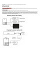
1. Install a bind plug into BATT/BIND connector.
2. Apply power to the receiver. It can be from 3.7 to 8.4 volts DC. Please refer to picture on the side of the receiver for the correct pinout
(GND, VCC, SIGNAL)
3. You will see the orange LED rapidly blinking. That means the receiver is in Bind mode.
4. Follow the procedures of your specific transmitter to enter Bind Mode, the system will connect within a few seconds. Once connected,
the orange LED on the receiver will blink several times and go solid indicating the system is connected.
If binding is not successful try to move receiver at least 2-3 meters from transmitter during binding. Receiver is extremely sensitive
and close proximity to the transmitter oversaturates it.
5. Remove the bind plug from the BIND and THRO ports on the receiver before you power off the transmitter and store it in a convenient
place.
After you’ve set up your model, it’s important to rebind the system so the true low throttle and neutral steering positions are set.
NOTICE:
Remove the bind plug to prevent the system from entering bind mode the next time the power is turned on.
S
MART
F
AILSAFE FEATURE
The GR300
R
features failsafe. It remembers the steering wheel and throttle trigger positions during the bind process with your transmitter.
(generally full brake and neutral steering). This stores the failsafe positions. Continue to hold the failsafe positions until the binding process is
complete. When the signal is regained, the system immediately regains control.
When the receiver only is turned on (no transmitter signal is present), the throttle channel has no output, to avoid operating or arming the
electronic speed control. All other channels are driven to their preset failsafe positions set during binding.
C
HANNEL
C
ONNECTOR
D
ESCRIPTION